
In the lesson, we will develop a stepper motor driver with computer control. I will talk about text-based communication protocol using AT commands. We will learn how to control a motor using the Arduino IDE serial port monitor and the top level program StepMotor.
Previous lesson List of lessons Next lesson
I set the task to develop an intelligent stepper motor driver based on an Arduino board. The driver must be able to control the motor from a computer through a standard Arduino board connection cable or through any other serial port.
The functionality of the device is determined by the StepMotor library from Lesson 29.
Hardware part of the driver.
To connect a unipolar motor to the Arduino board, I used the circuit from Lesson 28.
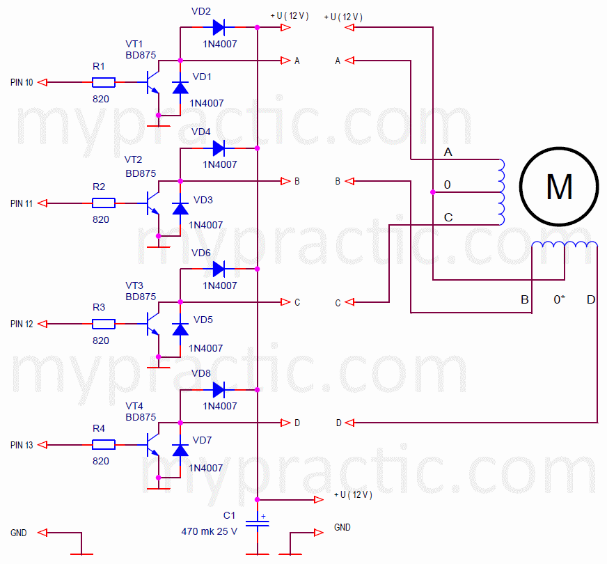
But you can apply any other circuit for unipolar or bipolar stepper motors.
I connected a fairly powerful fl57sth76-1006 motor. It has 400 steps per full revolution, phase current 1 A.

The resistance of the motor windings makes it possible to do without limiting resistors. For other types of motors, it may be necessary to either reduce the supply voltage or add a limiting resistor to each phase. This is written in Lesson 28 for a unipolar motor and will be discussed in the next lessons for a bipolar one.
Data exchange between an Arduino board and a computer.
The development of the software part of the driver comes down to receiving data from the computer and calling the functions of the StepMotor library from Lesson 29. We discussed the work with the StepMotor library in detail in that lesson. But we have not yet dealt with a full-fledged data exchange with a computer.
First of all, you need to define the exchange protocol. With the help of the serial port, we can exchange bytes. And we need to send commands, numbers. It is the protocol that determines how to interpret the sequence of bytes.
A data exchange protocol is a set of rules, agreements that define the exchange of data between programs. In our case, between the driver program of the Arduino board and the top-level program on the computer.
Protocols can be text and numeric. For example, the number "231" in the text protocol will be transmitted as 3 bytes with character codes "2", "3" and "1". And in a numerical protocol, to transmit the same number, it is enough to transmit one byte with a binary code 231. This example shows the main advantage of numerical protocols - to transmit the same amount of information, significantly less data is required.
But text-based protocols have their own advantage, due to which they are used more often than numeric ones. This is the ability to control, debug them using standard means - text terminals. When we debugged Arduino programs using the serial port, we sent the data to the computer in text format. We started the serial port monitor and saw on the computer screen voltage, or temperature, or some other data given in a form that we understand. But we could send data in binary code with the Serial.write (byte) command. There would be much less data, but to decrypt it, you would have to use a special program that understands what kind of data it is and how to interpret it.
Personally, I am a proponent of numeric protocols, especially for devices with limited resources. But for developing the driver, I chose a text protocol because of its versatility, simplicity of demonstration and debugging.
AT commands text exchange protocol.
AT commands is a simple text-based communication protocol in which each command begins with “AT” characters. Then the parameters and codes follow also in text form.
The sequence of symbols "AT" comes from the English "Attention" and means that a new command has come. The standard AT protocol response is “OK”.
AT commands are widely used to exchange data with modems, including GSM modules, WiFi, GPS modules and many other devices. We'll come back to AT commands in the lessons about wireless communication technologies.
AT commands of the stepper motor driver.
We will develop our data exchange protocol.
What commands do we need? If we are using the StepMotor library, then we need commands for each library function:
- initiate rotation for a given number of steps;
- set the switching and stopping modes of the motor;
- set the rotation speed;
- know the number of remaining steps;
- check the connection.
The exchange validation command was added to the commands corresponding to the library methods. We need to be able to find out if the driver is enabled.
The general format of the command looks like this:
- Each command line must start with “AT”.
- This is followed by a sequence of symbols - codes, numbers, parameters.
- It is customary to end the command with control characters "\ r" (carriage return, code 13) and "\ n" (line feed, code 10). These control codes were described in the previous lesson. The serial port monitor automatically adds "\ r \ n" to any data. Those. when you type "AT" in the monitor and press the "Enter" key, the monitor transmits 4 characters "AT \ r \ n".
- The response uses the sequence "OK \ r \ n". Thanks to the control characters, each response in the serial port monitor window will be displayed on a new line.
Using these rules, I selected the following AT command formats for the driver.
| Command | Response | Description |
| AT ( “AT”, 13, 10 ) |
OK ( “OK”, 13, 10 ) |
Checking the connection. Returns "OK". |
| ATS= steps ( “ATS=”, steps, 13, 10 ) |
OK ( “OK”, 13, 10 ) |
Initiates the motor rotation for the specified number of steps. |
| ATM= mode, fix ( “ATM=”, mode, “,”, fix, 13, 10 ) |
OK ( “OK”, 13, 10 ) |
Sets the motor control mode:
mode:
fix:
|
| ATD= divider ( “ATD=”, divider, 13, 10 ) |
OK ( “OK”, 13, 10 ) |
Sets the phase switching frequency, i.e. rotational speed. |
| ATR? ( “ATR”, 13, 10 ) |
steps, OK (steps, “OK”, 13, 10 ) |
Reads out the number of steps remaining before the motor stops. |
Usually text protocols treat lowercase and uppercase letters equally, but to simplify the program, I defined a protocol that supports only uppercase characters.
The protocol also lacks data integrity protection with control codes. But AT commands are usually used for devices located close to each other and there is no need for control codes. In addition, the presence of checksums will negate the main advantage of the text protocol - the ability to control from any text terminal. You can't calculate the control codes manually.
Implementation of the driver resident program.
The program can be downloaded from this link: sketch_31_1.
The TimerOne.h and StepMotor.h libraries must be installed. Both libraries are in Lesson 29.
I wrote in detail about working with the StepMotor library in that lesson. It remains to explain the block of data exchange with a computer.
The cycle loop () contains a program block for detection a command.
// exchange data with computer
letterNum= Serial.available(); // read the number of characters received
if ( letterNum == 0 ) {
// no data
timeOutCount= 0;
}
else {
// there is data
if ( letterNum != prevDataNum ) timeOutCount= 0; // new data
prevDataNum= letterNum; // overload the number of characters received
}
if ( timeOutCount > TIME_OUT ) {
// pause between data is longer than the timeout
// command accepted, decryption
The block works according to the following algorithm:
- Determines if new data has arrived at the port.
- If the data is received, it resets the timeOutCount counter.
- If the time counter timeOutCount has exceeded the TIME_OUT value, ie data has stopped arriving, it determines that the command is accepted and proceeds to decrypt the command.
In fact, the block allocates pauses between characters over 30ms (TIME_OUT). Then the characters are read from the serial port buffer and decrypted.
Note that the driver program does not hang the program. In loop (), you can still perform other tasks in parallel.
I will not describe the command decryption block. Sequential actions are performed in it: character codes are compared, numbers are converted, responses are formed. There are enough comments, you can figure it out yourself.
Testing the operation of the driver.
Upload the sketch to the Board, launch the Arduino IDE serial port monitor. Check the commands.
I specified parameters for my motor (400 steps per revolution).
| Send | Receive | Action |
| AT | OK | Communication check |
| ATD=20 | OK | Setting the speed |
| ATS=400 | OK | Full counterclockwise turn |
| ATS=-400 | OK | Full clockwise rotation turn |
| ATS=1 | OK | Step counterclockwise |
| ATS=-1 | OK | Step clockwise |
| ATM=1,0 | OK | Set half step mode |
| ATS=800 | OK | 2 turns counterclockwise rotation |
| ATS=-800 | OK | 2 turns clockwise rotation |
| ATS=30000 | OK | Counterclockwise rotation |
| ATR? | 3772OK | Reading the remaining steps |
| ATR? | 3410OK | Reading the remaining steps |
| ATR? | 3052OK | Reading the remaining steps |
| ATS=0 | OK | Stop |
As you can see, the motor can be controlled using a standard program - a serial port monitor. There are many similar monitors, terminals with which you can send commands. You just need to set the speed to 9600 and the mode of adding control characters "carriage return", "line feed" at the end of the command. In the serial monitor, the mode is selected at the bottom right of the window and is called "NL & CR".
Top-level program StepMotor for stepper motor control.
I developed a simple program to control a stepper motor from a computer through a driver on the Arduino board. The program supports all available modes.
You can download the program at this link.
Connection, first start, port selection is the same as in the Thermometer program from Lesson 24. I will only say that it is more convenient to use the virtual port, which forms the driver of the Arduino board when the board is connected to the computer. It is optional to run the Arduino IDE. The first time you turn it on, you need to select a port number in StepMotor. The program will remember it and will use it on subsequent runs.
The main program window looks like this.

The "Steps" panel allows you to initiate rotation of the motor by a specified number of steps. Steps are set with a slider or in an editable window and are sent to the driver with the "->" button to the right of the panel.
Using the "Speed" panel, you can set the value of the step commutation divider, and hence the rotation speed. It is loaded into the driver using the "->" button to the right of the panel.
The "Mode" panel allows you to set the phase switching mode and select the motor stop mode.
It should be remembered that the parameters specified in these three panels are sent to the driver by pressing the "->" buttons to the right of the corresponding panels.
The "Motor parameters" panel sets the number of motor steps per full revolution and the phase switching period with the divider equal to 1. In my resident program for the driver, the period is 250 µs (timer interrupt), but you can specify a other switching frequency. Then this parameter must be changed in the top-level program. Data from the "Motor parameters" panel is not loaded into the driver, but is used to calculate the speed in the "Speed" panel.
In the "Driver" panel:
- The number of remaining steps is displayed. This parameter is permanently read from the driver in a loop.
- The "Stop" button stops the engine in any mode.
- Button ”<<” starts the engine in continuous counterclockwise rotation.
- Button ”>>” starts the motor in continuous clockwise rotation.
- Button "+1 step" makes the motor take one step counterclockwise.
- Button ”-1 step” makes the motor take one step clockwise.
- The “Exchange” LED indicates the communication status. Red means error, green means normal operation.
The program allows you to easily check the operation of the driver in all modes. But the main goal is to show the principle of controlling the Arduino controller from a computer using the AT commands protocol. We will use this program in subsequent lessons about connecting a bipolar motor and a driver based on the TB6560-V2 module to the Arduino.
In the next lesson I will try to make an open-loop servo system based on this stepper motor driver.