In all the articles on stepper motors, I never tired of repeating that a stepper motor combines an electric drive and a positioning device without feedback. In this lesson, I want to demonstrate the use of a stepper motor in an electric drive positioning system.
Previous lesson List of lessons Next lesson
In the lesson, I developed two servo systems with a stepper motor as an electric drive.
- One uses a driver based on the Arduino board from the previous lesson and is controlled from a computer.
- The second servo drive is a stand-alone device in which the position of the motor shaft is set by a variable resistor.
You will see how easy it is to implement such systems based on a stepper motor. But first, I will talk about what a motor positioning system is and how it is created according to the traditional scheme.
Motor positioning system.
This is a very complex topic that includes several technical disciplines such as electrical machines, automatic control theory, electronics, and many others. I will only touch on the most general concepts.
A motor positioning system is an electric drive that implements a change in the position of an actuator in accordance with a reference signal that can arbitrarily change over time.
Simply put, a low-power input signal at the input of the servo drive controls a powerful mechanical load with a certain precision. We move the image of an arrow on the computer screen or turn the knob of a variable resistor, and the shaft of a powerful motor turns.
In the general case, the block diagram of the servo system of an electric drive looks like this.
The rotor position sensor is mechanically connected to the motor shaft. The sensor converts the angle of the shaft position into a physical value with which the regulator operates. This can be a voltage for an analog regulator or a digital code for computing systems. Then the measured angle is compared with the specified one, and the mismatch error is calculated. The error is sent to the regulator, which generates motor power signals, trying to compensate for the difference between the set and real angles. A variety of types of motors can be used as a drive, from low-voltage collector motors to powerful asynchronous motors.
The diagram consists of three rectangles, but in fact the servo drive is a very complex system. A sufficiently accurate angle sensor is required. The operation of the regulator is complicated by the inertia of the motor and load. It is extremely unpleasant to work with a non-linear load. Such systems are built on the principle of proportional-integral-differential controllers. Adaptive control algorithms are often used.
The principle of the implementation of the servo drive on a stepper motor.
It is much easier to implement a positioning electric drive system on a stepper motor. The main feature of a stepper motor is that the position of the rotor can always be calculated by counting the number of steps taken.
The system counts the steps taken and thus determines the current position of the rotor. When the set point value of the shaft position is changed, the system calculates the difference between the actual and set angles, and takes the required number of steps to compensate for the mismatch error. No feedback, no need for a rotor position sensor.
The advantages of a servo drive based on a stepper motor include:
- ease of implementation;
- absence of a rotor position sensor;
- there is no over-regulation, oscillatory processes.
Disadvantages:
- the need for initial synchronization of the real rotor position and the value of the rotor position in the system controller;
- when the stepper motor is out of sync, the system will operate with an error that can only be compensated for by resynchronizing.
Motor positioning system controlled by a computer.
To implement this device, I used the stepper motor driver from the previous lesson. The same scheme for connecting the motor to the Arduino board, the same driver resident program controlled from a computer using the AT command protocol.
The entire control algorithm is implemented in a top-level program on a computer.
- The program stores the current position of the motor rotor.
- When the angle setpoint is changed, it calculates the number of steps the motor must take to compensate for the error. It then sends the AT command to take the required number of steps.
- With the AT command to read the remaining steps, the program waits for the motor to stop and, if necessary, generates the next command to turn the rotor.
- The position of the motor shaft is displayed on the computer monitor.
I named the program Tracker. You can download it at this link.
The connection options, first start, the port number setting are absolutely the same as in the Thermometer program (Lesson 24). For testing, it is more convenient to use the virtual port that the Arduino driver creates when the board is connected to the computer. You do not need to run the Arduino IDE program for this.
I repeat once again that the motor connection diagram and the sketch of the program for the Arduino board can be taken from the previous lesson. Actually, we are using the device developed in the previous lesson - an intelligent stepper motor driver. The servo drive is one example of the driver application.
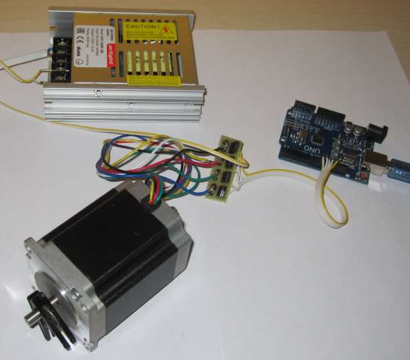
My assembled device looks like this.
The clothespin acts as an arrow for the position of the motor shaft.
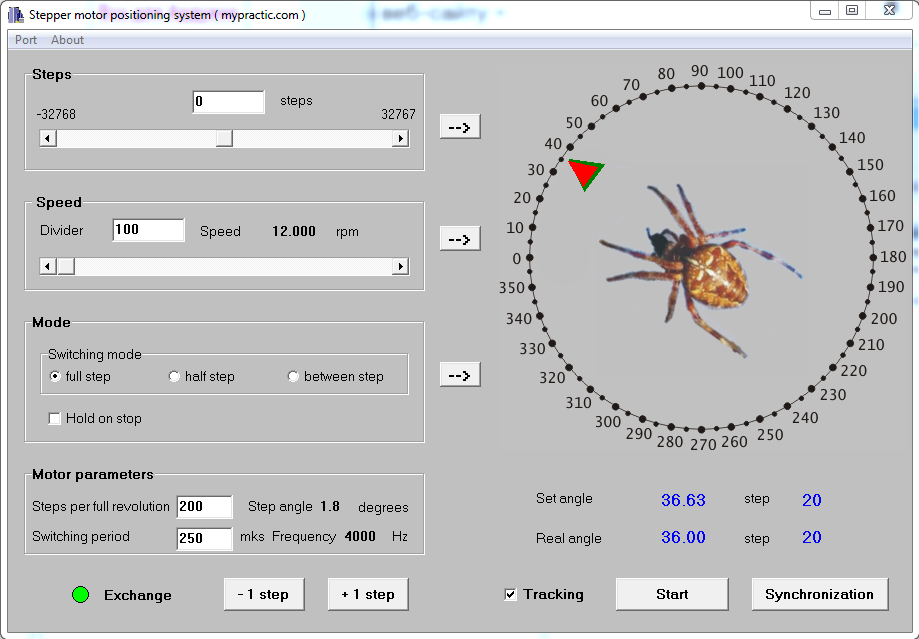
The Tracker program window looks like this.
Some of the graphical controls are similar to the components of the StepMotor program from the previous lesson.
- Panel "Speed" allows you to set the speed of rotation.
- Using the “Mode” panel, you can set the phase commutation and motor stop mode.
- The "Steps" panel allows you to make an arbitrary number of steps.
You just need to remember that the data from these three panels is transferred to the driver by pressing the "->" buttons next to the corresponding panels.
- Using the "Motor Parameters" panel, you can set the number of steps of the motor per full revolution and the phase switching period in the driver program (in my program 250 µs).
- The "Exchange" LED indicates the state of communication between the computer and the driver. Should be green in normal mode.
- Buttons “- 1 step” and “+ 1 step” allow you to take one step clockwise and counterclockwise.
The program has new elements for controlling the servo drive.
First of all, this is the scale for the angle of the motor shaft position.
There are two pointers on it:
- the set angle - green triangle;
- the real angle is a red triangle.
The real angle marker is followed by a spider in the center of the scale. I love insects. I caught a Xylocop this summer. I wanted to use it in the program, but to save time I took an image of a spider from the old program. By the way, from the program of the positioning system based on a powerful inductor motor.
The specified angle pointer can be moved with the mouse to change the specified angle. Below the scale there are numerical indicators of the set and real angles, as well as the corresponding motor steps.
The active "Tracking" checkbox means that when the pointer of a given angle is moved, the engine quickly (in real time) works out the position. Those. the real motor shaft follows the green pointer.
If there is no "Tracking" checkbox, then the set value is tracked only by pressing the "Start" button.
The "Synchronization" button sets both pointers to zero position. Used to set the starting position of the motor.
I made a short film about the servo drive.
I turned the motor in different directions, but the zero angle on the program scale corresponded to the same position of the real motor shaft. It is only necessary to take into account that this rule is strictly fulfilled in the rotor fixation mode when the engine stops, especially for the half step and between step switching modes. In phase-off mode when stopped, the position of the motor shaft may change due to mechanical load or inertia.
Just remember that in the rotor fixing mode, when the motor is stopped, current always flows through the drivers. Heatsinks must be installed on the driver transistors. Otherwise, they may overheat and burn.
Arduino project of a stepper motor positioning electric drive with a variable resistor control.
I decided to implement the second version of the servo drive without feedback as an autonomous device, in which the specified angle is set by a variable resistor.
The unipolar stepper motor driver is connected to the Arduino board according to the diagram from the previous lesson. However, you can use any other circuit for a unipolar or bipolar stepper motor.
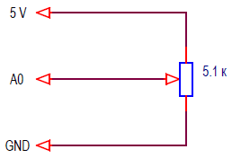
A variable resistor is connected to the analog input A0 of the board according to this scheme.
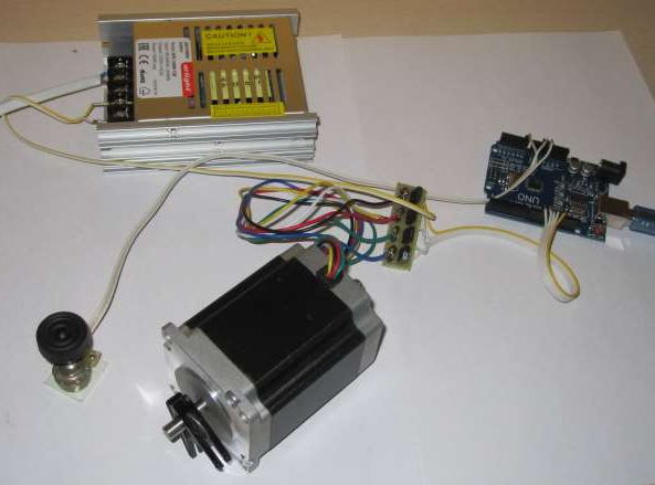
My assembled device looks like this.
The servo drive should rotate the motor shaft following the movement of the resistor shaft.
Resident program of the stepper motor servo drive on Arduino.
The sketch of the program can be downloaded from this link sketch_32_1.
I hope you already have the TimerOne.h and StepMotor.h libraries installed.
The sketch of the program is small.
// open-loop servo system based on a stepper motor
#include <TimerOne.h>
#include <StepMotor.h>
#define MEASURE_PERIOD 80 // measurement period time (* 250 μs)
#define numStepsMotor 400 // number of motor steps per revolution
int timeCount; // time counter
long sumU; // переменные для суммирования кодов АЦП
long averageU; // variable for summing ADC codes
int currentStep; // current position of the motor
int setStep; // set motor position
StepMotor myMotor(10, 11, 12, 13); // create an object of the StepMotor type, set pins for the phases
void setup() {
Timer1.initialize(250); // initialization of timer 1, period 250 μs
Timer1.attachInterrupt(timerInterrupt, 250); // set the interrupt handler
myMotor.setMode(0, false); // step mode, no fixing on stop
myMotor.setDivider(15); // frequency divider 15
}
void loop() {
// check motor stop
if( myMotor.readSteps() == 0) {
// motor stopped
// calculation of the set position
setStep = averageU * (numStepsMotor - 1) / 1023 / MEASURE_PERIOD;
// determine how many steps to take
int stepsToDo; // сhow many steps to take
stepsToDo = currentStep - setStep; // mismatch error
if( abs(stepsToDo) >= (numStepsMotor / 2) ) {
if((stepsToDo) > 0) stepsToDo -= numStepsMotor;
else stepsToDo += numStepsMotor;
}
myMotor.step(stepsToDo); // motor starting
currentStep = setStep; // overload the current position
}
}
//-------------------------------------- 250 μs interrupt handler
void timerInterrupt() {
myMotor.control(); // motor control
sumU += analogRead(A0); // summation of ADC codes
timeCount++; // +1 counter of averaging samples
// check the number of averaging samples
if ( timeCount >= MEASURE_PERIOD ) {
timeCount= 0;
averageU= sumU; // overload of the average value
sumU= 0;
}
}
The program measures and averages the voltage value at the analog input A0. This block is described in lesson 13.
When the motor is stopped, it is checked whether there is a difference between the specified and real angles of the rotor position. The step() function is called if necessary to turn the motor shaft.
Here is a short film about the operation of the device.
My motor has 400 steps per revolution. If you are using a different engine, then you need to change the line
#define numStepsMotor 400 // number of motor steps per revolution
The motor operates in step mode without fixing the rotor when stopped. The mode is assigned in the setup block and can be easily changed. In half step mode, the number of motor steps must be set twice as large. In my case:
#define numStepsMotor 800 // number of motor steps per revolution
In some positions of the variable resistor, the ADC value jerks by one unit. A common phenomenon for analog signal conversion. The stepper motor responds to this change in the set angle, which is reflected in the twitch of the shaft. I did not compensate for this effect, because the program is more demo.
Unexpectedly, the first practical application of a variant of the positioning system with a variable resistor was found. Anton needed to make a large analogue volume indicator. Obviously for decorative purposes. Instead of a variable resistor - a position controller, he applied an amplified analog signal, added a second channel and an initial setting of the arrows to the extreme left position. Here's what happened.
I understand that in the final version the device will be designed in the form of large arrow indicators.
In this lesson, I wanted to show the main advantage of a stepper motor - the ability to position without feedback. I hope you appreciated the simplicity of creating tracking systems based on this principle.
Here is a link to another real servo system project implemented in this way. There are two motors connected to the Arduino Nano board, which track the position according to the data set from the DMX interface.
In the next lesson, we will connect a bipolar stepper motor to the Arduino. All programs from the previous lessons should work unchanged and with a bipolar motor.


