With this lesson, I begin a series of articles on switching stabilizer, pulse width modulation regulators, and output power control devices.
Previous lesson List of lessons Next lesson
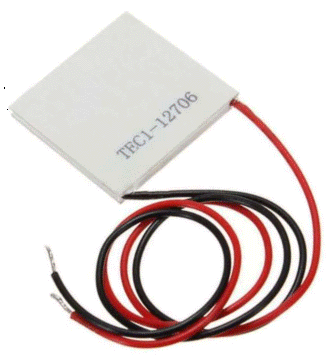
The goal I set is to develop a controller for a refrigerator with Peltier module.
We will make an analog of my development "Peltier module controller using a PIC chip", only implemented on the basis of an Arduino board.
- Many people were interested in this development, and letters rained down on me with requests to implement it using Arduino.
- The development is ideal for learning about the hardware and software of digital regulators. In addition, it combines many of the tasks studied in previous lessons:
- measurement of analog signals;
- work with buttons;
- connection of display systems;
- temperature measurement;
- work with EEPROM;
- communication with a computer;
- parallel processes;
- and much more.
I will conduct the development sequentially, step by step, explaining my actions. What will be the result - I do not know. I hope for a full-fledged working project of the refrigerator controller.
I don't have a finished project. I will write lessons according to the current state, so during the tests it may turn out that at some stage I made a mistake. I will correct. This is better than I will debug the development and give out ready-made solutions.
Differences between the development and the prototype.
The only functional difference from the prototype development on the PIC controller is the absence of a fast voltage regulator that compensates for the supply voltage ripples.
Those, this version of the device must be powered by a stabilized power supply with a low level of ripple (no more than 5%). All modern switching power supplies meet these requirements.
And the power supply option from an unstabilized power supply (transformer, rectifier, capacitive filter) is excluded. The performance of the Arduino system does not allow the implementation of a fast voltage regulator.
Development of the overall structure of the device.
At this stage, it is necessary to understand in a general way:
- what elements the system consists of;
- using which controller to make it;
- whether there are enough pins and functionality of the controller.
I imagine the controller as a “black box” or “garbage pit” and connect everything I need to it. Then I look if, for example, the Arduino UNO R3 board is suitable for these purposes.
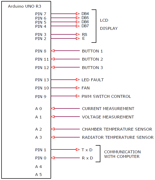
In my interpretation it looks like this.
I drew a rectangle - the controller and all the signals necessary to connect the elements of the system.
I decided that it is necessary to connect to the board:
- LCD display (for displaying results and modes);
- 3 buttons (for control);
- fault indication LED;
- fan control switch (to turn on the hot side radiator fan);
- pulse stabilizer switch (for adjusting the power of the Peltier module);
- analog input for measuring the load current;
- analog input for measuring load voltage;
- chamber temperature sensor (accurate 1-wire sensor DS18B20);
- radiator temperature sensor (haven't decided which sensor yet, probably also DS18B20);
- signals of communication with the computer.
There are 18 signals in total. The Arduino UNO R3 or Arduino NANO board has 20 pins. There are still 2 pins left in reserve. Maybe you want to connect another button, or an LED, or a humidity sensor, or a cold side fan ... We need 2 or 3 analog inputs, the board has 6. That is, everything suits us.
You can assign pin numbers immediately or during development. I identified them right away. The connection takes place using connectors, you can always change. Keep in mind that pin assignments are not final.
Pulse regulators.
To accurately stabilize the temperature and the operation of the Peltier module in optimal mode, it is necessary to adjust the power on it.
Regulators are analog (linear) and pulse (switching).
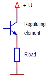
Analog regulators are a regulating element and a load connected in series to a power source. By changing the resistance of the regulating element, the voltage or current on the load is adjusted. As a regulating element, as a rule, a bipolar transistor is used.
The regulating element operates in linear mode. It is allocated "extra" power. At high currents, stabilizers of this type are strongly heated, have a low efficiency. A typical linear voltage regulator is the 7805 chip.
This option does not suit us. We will make a pulse (switching) stabilizer.
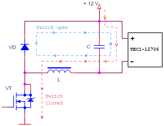
Switching stabilizers are different. We need a step-down switching regulator. The load voltage in such devices is always lower than the supply voltage. The circuit of the step-down switching regulator looks like this.
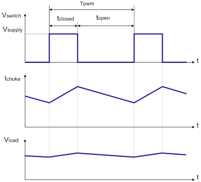
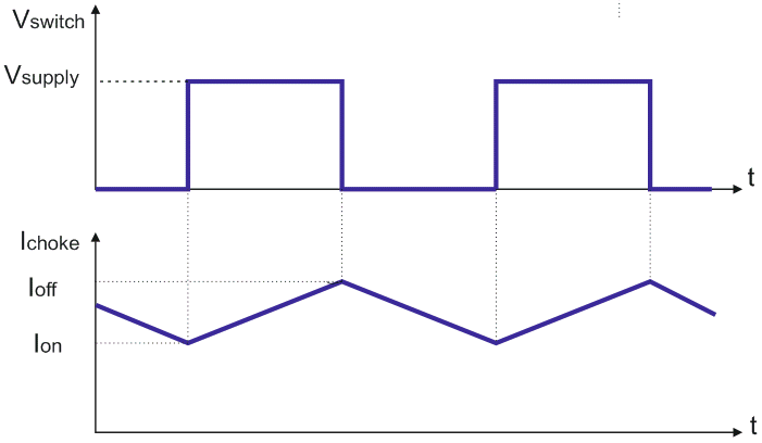
And this is a diagram of the operation of the regulator.
The transistor VT operates in the switching mode, i.e. it can only have two states: closed or open. The control device, in our case a microcontroller, switches the transistor with a certain frequency and duty cycle.
- When the transistor is closed, current flows through the circuit: power supply, transistor switch VT, inductor L, load.
- When the switch is open, the energy stored in the inductor is supplied to the load. Current flows through the circuit: inductor, VD diode, load.
Thus, the DC voltage at the output of the regulator depends on the ratio of the time of the closed (tclosed) and open switch (topen), i.e. on the duty cycle of the control pulses. By changing the duty cycle, the microcontroller can change the voltage at the load. Capacitor C smooths out the output voltage ripple.
The main advantage of this method of regulation is high efficiency. The transistor is always on or off. Therefore, little power is dissipated on it - always either the voltage across the transistor is close to zero, or the current is 0.
This is a classic circuit of a pulse step-down regulator. In it, the switching transistor is torn off from the common wire. The transistor is difficult to control, special bias circuits to the supply voltage bus are required.
So I changed the circuit. In it, the load is disconnected from the common wire, but the switch is tied to the common wire. This solution allows you to control the transistor switch from the microcontroller signal using a simple current driver-amplifier.
- When the switch is closed, the current flows to the load through the circuit: power supply, inductor L, tranzistor VT (the path of the current is shown in red).
- When the switch is open, the energy accumulated in the inductor is returned to the load through the regenerative diode VD (the current path is shown in blue).
Practical implementation of the switching regulator.
We need to implement a switching regulator node with the following functions:
- actual switching regulator (switch, choke, regenerative diode, smoothing capacitor);
- load voltage measurement circuit;
- regulator current measurement circuit;
- hardware overcurrent protection.
I, practically without changes, took the regulator circuit from the device on the PIC controller.
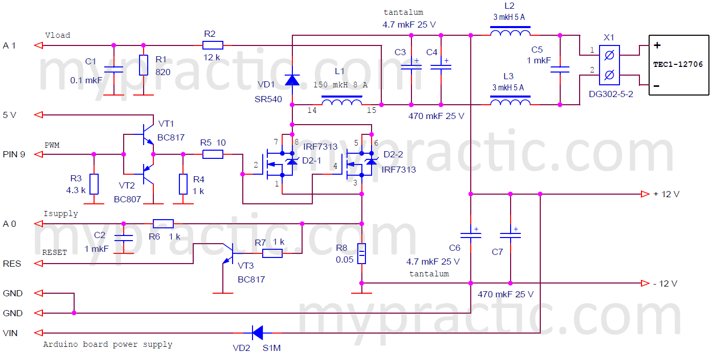
The circuit of the pulse regulator for working with an Arduino board.
I used MOSFET transistors IRF7313 as a power switch. In an article on increasing the power of the Peltier module controller, I wrote in detail about these transistors, about a possible replacement, and about the requirements for switch transistors for this circuit. Here is a link to the technical documentation IRF7313.pdf.
Using transistors VT1 and VT2, a MOSFET transistor driver is assembled. It's just a current amplifier, it even weakens the signal by voltage to about 4.3 V. Therefore, the switching transistor must be low-threshold. There are different ways to implement MOSFET drivers. Including using integrated drivers. This option is the easiest and cheapest.
To measure the voltage at the load, a divider R1, R2 is used. With such resistor values and a reference voltage source of 1.1 V, the measurement range is 0 ... 17.2 V. The circuit allows you to measure the voltage at the second load terminal relative to the common wire. We calculate the voltage at the load, knowing the voltage of the power source:
Vload = Vsupply - Vmeasured.
It is clear that the measurement accuracy will depend on the stability of maintaining the voltage of the power source. But we do not need high accuracy in measuring voltage, current, load power. We need to accurately measure and maintain only the temperature. We will measure it with high accuracy. And if the system shows that the Peltier module has a power of 10 W, but in fact it will be 10.5 W, this will not affect the operation of the device in any way. This applies to all other energy parameters.
The current is measured using a resistor-current sensor R8. Components R6 and C2 form a simple low pass filter.
The simplest hardware protection is assembled on the R7 and VT3 elements. If the current in the circuit exceeds 12 A, then the voltage on the resistor R8 will reach the transistor threshold of 0.6 V. The transistor close the RES (reset) pin of the microcontroller to ground. Everything should turn off. Unfortunately, the threshold for such protection is determined by the base-emitter voltage of a bipolar transistor (0.6 V). Because of this, the protection only works at significant currents. You can use an analog comparator, but this will complicate the circuit.
The current will be measured more accurately when the resistance of the current sensor R8 increases. But this will lead to the release of significant power on it. Even with a resistance of 0.05 ohms and a current of 5 A, 5 * 5 * 0.05 = 1.25 watts is dissipated on the resistor R8. Note that resistor R8 has a power of 2 watts.
Now, what current are we measuring. We measure the current consumption of the switching regulator from the power supply. The circuit for measuring this parameter is much simpler than the circuit for measuring the load current. Our load is “untied” from the common wire. For the system to work, it is necessary to measure the electric power on the Peltier module. We calculate the power consumed by the regulator by multiplying the power supply voltage by the current drawn. Let's assume that our regulator has an efficiency of 100% and decide that this is the power on the Peltier module. In fact, the efficiency of the regulator will be 90-95%, but this error will not affect the operation of the system in any way.
Components L2, L3, C5 are a simple RFI filter. It may not be necessary.
Calculation of the choke of the switching stabilizer.
The choke has two parameters that are important to us:
- inductance;
- saturation current.
The required inductance of the inductor is determined by the PWM frequency and the allowable inductor current ripple. There is a lot of information on this subject. I will give the most simplified calculation.
We apply voltage to the inductor and the current through it begins to increase. Increase, and not appear, because some current was already flowing through the inductor at the time of switching on (Ion).
The transistor is on. The voltage is connected to the inductor:
Vchoke = Vsupply - Vload.
The current through the inductor began to increase according to the law:
Ichoke = Vchoke * tclosed / L
- tclosed – closed switch pulse duration;
- L - inductance.
Those. the value of the ripple current of the inductor or how much the current has increased during the time of the closed switch is determined by the expression:
Ioff - Ion = Vchoke * tclosed / L
The load voltage may change. And it determines the voltage at the choke. There are formulas that take this into account. But in our case, I would take the following values:
- supply voltage 12 V;
- minimum voltage on the Peltier module 5 V;
- so the maximum voltage on the inductor 12 - 5 = 7 V.
The duration of the pulse of the closed switch is determined by the frequency of the PWM period. The higher it is, the less inductance the inductor needs. The maximum PWM frequency of the Arduino board is 62.5 kHz. I will tell you how to get such a frequency in the next lesson. We will use it.
Let's take the worst case - PWM switches exactly in the middle of the period.
- Period duration 1/62500 Hz = 0.000016 sec = 16 µs;
- Closed switch duration = 8 µs.
Current ripple in such circuits is usually set to 20% of the average current. Not to be confused with output voltage ripple. They are smoothed out by capacitors at the output of the circuit.
If we allow a current of 5 A, then we take a current ripple of 10% or 0.5 A.
Now you can calculate the inductance of the inductor:
L = Vchoke * tclosed / Iripple = 7 * 8 / 0.5 = 112 μH.
Inductor saturation current.
Everything in the world has a limit. And the choke too. At some current, it ceases to be an inductance. This is the saturation current of the inductor.
In our case, the maximum inductor current is defined as the average current plus ripple, i.e. 5.5 A. But it is better to choose the saturation current with a margin. If we want hardware protection to work in this version of the circuit, then it must be at least 12 A.
The saturation current is determined by the air gap in the inductor's magnetic core. In articles about Peltier module controllers, I talked about the design of the choke. If I start to expand this topic in detail, then we will leave Arduino, programming, and I don’t know when we will return.
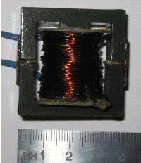
My inductor looks like this.
Naturally, the inductor winding wire must be of sufficient cross section. The calculation is simple - the determination of heat losses due to the active resistance of the winding.
Active winding resistance:
Ra = ρ * l / S,
- Ra – winding active resistance;
- Ρ – resistivity of the material, for copper 0.0175 Ohm mm2/m;
- l – winding length;
- S – winding wire section.
Thermal losses on the active resistance of the inductor:
P = I2 * Ra
General recommendations for mounting the device.
The switching regulator draws significant current from the power supply and this current must not be allowed to pass through the Arduino board. The diagram shows that the wires from the power supply are connected directly to the blocking capacitors C6 and C7.
The main pulse currents of the circuit pass through the circuit C6, load, L1, D2, R8. This circuit must be closed by connections with a minimum length.
The common wire and power bus of the Arduino board are connected to the blocking capacitor C6.
The signal wires between the Arduino board and the switching regulator module must be of the minimum length. Capacitors C1 and C2 are best placed on the connectors to the board.
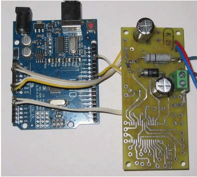
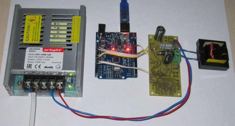
I assembled the circuit on the Peltier module controller board. Soldered only the necessary components. My assembled device looks like this.
I set the PWM to 50% and checked the operation of the circuit. The device is working correctly.
In the next lesson, we will control all this.

