
With this publication, I begin a series of lessons about stepper motor control in the Arduino system. The first lesson is devoted to connecting unipolar stepper motors to Arduino.
Previous lesson List of lessons Next lesson
A stepper motor is a unique electromechanical device that combines a motor and a positioning device without feedback. The use of stepper motors greatly simplifies the mechanical design of any equipment. They are absolutely indispensable in various fields of engineering: in CNC machines, robotics, in industrial equipment...
It is assumed that the reader is well acquainted with the principle of operation and methods of controlling stepper motors, with terminology in this area. If not, read this article carefully. It tells about stepper motors very simply.
Connecting a unipolar stepper motor to an Arduino Board.
The stepper motor cannot be connected directly to the microcontroller pins. Insufficient load capacity for current and voltage at the outputs of the microcontroller. It is necessary to use an amplifier of control signals - a driver.
To control a unipolar stepper motor, 4 switches are enough, commuting 4 windings to the ground. I will give two practical schemes for unipolar drivers: on bipolar transistors and MOSFET transistors.
The driver circuit of a unipolar stepper motor on bipolar transistors looks like this.

The driver allows switching loads with currents up to 1 A and voltage up to 45 V.
It is much preferable to use MOSFET transistors.

The circuit assembled on MOSFET transistors IRF7313 (irf7313.pdf) has the following parameters:
- maximum permissible current 6.5 A;
- maximum voltage 30 V;
- resistance of closed transistor 0.029 Ohm;
- gate threshold voltage 1 V;
- packed - so-8 miniature case;
- in the case two transistors.
The unipolar motor driver made on MOSFET transistors has significant advantages over a similar device on bipolar transistors:
- does not require radiators for transistors cooling;
- has very low loss in open switches;
- has small dimensions;
- only two cases with 8 pins each are used.
In both schemes, the switches are controlled directly from the microcontroller pins by the CMOS logic levels (0 / +5 V). A high signal level opens the switch, and current flows through the motor winding. The diodes protect the switches from voltage surges during switching.
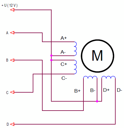
The circuit diagrams show the connection of stepper motors with 6 pins.
For example, for widespread motors FL20STH, FL28STH, FL35ST, FL39ST, FL42STH, FL57ST, FL57STH with a 6-wire winding configuration, the terminals are marked in the following colors.
| Designation of the motor terminals on the diagram | Wire color |
| A | black |
| 0 | yellow |
| C | green |
| B | red |
| 0* | white |
| D | blue |
The 5-wire configuration is a variant in which the common winding wires are connected inside the motor. There are such engines. For example, PM35S-048.
There are motors with 8 pins. Each winding has separate pins.
The wiring diagram is the same, only the connections between the windings occur outside the motor.
Advantages and disadvantages of simple unipolar stepper motor drivers.
The above driver schemes are very simple – 4 switches without current feedbacks. This is the main advantage of unipolar stepper motor drivers.
To control such drivers, very simple software modules are used, the microcontroller resources are used only slightly. It is enough to change the state of the 4 pins of the microcontroller in a certain sequence.
- The main disadvantage is the lack of stabilization of the winding currents.
- In static mode, the current is determined by the active resistance of the motor winding and the supply voltage (according to Ohm's law I = U / R). Thus, only motors with a certain resistance of the windings can be used in the circuit, or it is necessary to select the supply voltage. This requirement significantly narrows the choice of motors.
You can limit the phase currents with additional resistors connected in series with each winding. The solution is quite working, but with powerful motors, these resistors dissipate quite a lot of power.
- Lack of current stabilization also leads to a second problem. This is a slow current rise rate associated with significant inductance of the windings. This leads to a significant reduction in the maximum engine speed. For example, the motor FL57STH76-1006 has a winding inductance of 14 mH. At a voltage of 12 V, the current in the winding will reach the operating value of 1 A only after 1.2 ms (I = U * T / L). At high rotational speeds, phase currents will be significantly lowered, which means that engine power will also decrease.
The resistors connected in series with the windings partially correct this problem, but dissipate the excess power.
- To the disadvantages of the driver, one can add that a unipolar stepper motor has lower power compared to a bipolar stepper motor with the same dimensions. Power is reduced by about 40%.
Despite the disadvantages, such connection schemes for unipolar stepper motors are widely used. For example, in the first versions of our machine for filling and sealing ampoules, all engines operate in unipolar mode.
We continue to connect the stepper motor to the Arduino board. I soldered the driver using bipolar transistors and connected PM35S-048 motor to it. The resistance of my motor windings is 36 ohms. The current at 12 V is 0.33 A. The motor can be connected to the driver without limiting resistors.

I was afraid to use a solderless breadboard. Too high currents.
Stepper is the standard Arduino library for stepper motor control.
The Arduino IDE package has a standard library for controlling unipolar and bipolar stepper motors. It does not need to be searched and downloaded from the Internet. It is installed with the Arduino IDE package. The library is very simple. In addition to the constructor, it has only two functions.
Stepper (steps, pin1, pin2, pin3, pin4)
Constructor of the Stepper class. Creates an object of type Stepper.
Parameters:
- steps - the number of motor steps per revolution (360 °). The parameter is used by the setSpeed () function to calculate the rotation speed.
- pin1, pin2, pin3, pin4 - pins for connecting the motor driver. For a two-wire connection, pin3 and pin4 are not used. For a four-wire circuit, pin1, pin2, pin3, pin4 correspond to phases A, C, B, D in a unipolar control mode.
Stepper motor1 (400, 10, 11, 12, 13); // create an object motor1
void setSpeed (long rpms)
Sets the motor speed in revolutions per minute.
Parameters:
- rpms - rotation speed in revolutions per minute.
motor1.setSpeed (60); // set the rotation speed to 60 rpm. in min
void step (int steps)
Causes the motor to rotate by the specified number of steps. The function stops the execution of the program until it completes.
Parameters:
- steps – the number of steps to rotate the motor rotor by. A negative value rotates the motor in the opposite direction.
motor 1.step(20); / / perform 20 steps counterclockwise
Simple stepper motor control program.
The program controls the motor according to the following algorithm:
- the motor perfoms 5 revolutions counterclockwise;
- stops for 1 second;
- perfoms 5 turns clockwise;
- stops for 1 second;
- and so on in an infinite loop.
The program sketch is simple and obvious.
// simple stepper motor control program using the Stepper library
// perfoms 5 turns counterclockwise at a speed of 1 revolution per second
// after a pause of 1 second, makes 5 turns clockwise
#include <Stepper.h>
Stepper motor(48, 10, 12, 11, 13); // motor object, 48 steps per revolution
void setup() {
motor.setSpeed(60); // speed of 60 rpm in minutes
}
void loop() {
motor.step(240); // 5 turns (240 steps) clockwise
delay(1000);
motor.step(-240); // 5 turns (240 steps) counterclockwise
delay(1000);
}
I just want to note that in the four-wire mode, Stepper object switches phases in the following sequence.
| Step | Pin 1 | Pin 2 | Pin 3 | Pin 4 |
| 1 | 1 | 0 | 1 | 0 |
| 2 | 0 | 1 | 1 | 0 |
| 3 | 0 | 1 | 0 | 1 |
| 4 | 1 | 0 | 0 | 1 |
It can be seen that:
- Two phases are always enabled, i.e. the unipolar motor operates in two phase on full step mode.
- PIN1, pin2, pin3, pin4 pins correspond to phases A, C, B, and D.
Disadvantages of the Stepper library.
The Stepper library has only one advantage - a wide enough range of speed control. The phase switching time is calculated by constantly calling the micros () function and comparing the time values of this function. For everything else, the resources of the microcontroller are not enough.
There are so many disadvantages of the Stepper library that I don’t know how it can be used in practical applications.
- The main drawback is that calling the step () method suspends the program. All resources are spent on counting the phase switching time. Even if you run a parallel process through a timer interrupt, it will disrupt the phase switching countdown. Those, when the engine is spinning, nothing else can be done in the program. Probably, with the help of this library you can only make a fan, and even then without the switch or speed controller.
- As a consequence of the previous paragraph, it is impossible to control several motors simultaneously.
- The Stepper library controls a unipolar stepper motor only in two phase on full step mode. But there are also step and microstepping modes that are implemented by simple software methods and are often necessary in practice. The bipolar motor can only work in step mode.
- It is not possible to stop the engine until all steps specified by the step () function have been completed.
- When the motor is stopped, it is in a fixed position and current continues to flow through the windings. In some applications, it is necessary to turn off the current. There is no choice of the motor stop mode in the Stepper library.
In the next lesson, I will introduce a stepper motor control library that is free of these drawbacks. Motor control takes place in a parallel process. The library supports all the modes listed above.