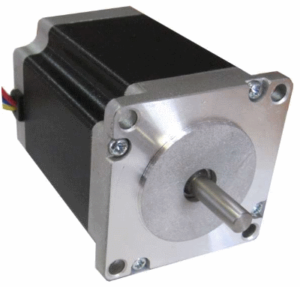
In many of my developments, I use stepper motors. There are branches of precision mechanics in which they are irreplaceable. I will try to explain as simply as possible how the stepper motor operates, what it is.
A stepper motor is a brushless synchronous motor, the rotor of which performs discrete movements (steps) of a certain value with fixing the position of the rotor at the end of each step.
The rotor moves in steps of a known magnitude. By counting the steps, you can determine how much the position of the rotor has changed, and calculate its absolute position.
Combining a motor and a positioning device without feedback, a stepper motor is an ideal drive in industrial equipment, CNC machines, robotics...
Principle of operation of stepper motors
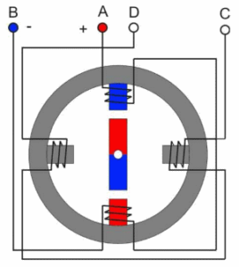
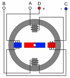
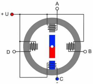
Imagine a two-pole permanent magnet on the motor shaft – this is a rotor. It is surrounded by a closed magnetic circuit with four windings – a stator. More correctly, it is two windings AB and CD with halves located on opposite poles of the stator.
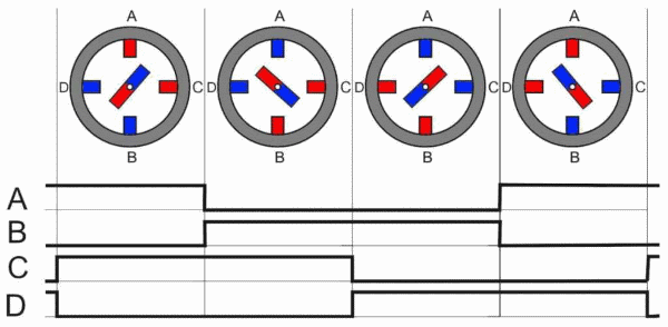
Connected to the voltage source winding AB (polarity + -) as shown in the figure. The current in this winding will cause the magnetic field of the stator to appear with the poles at the top N, at the bottom S.
As you know, the opposite poles of magnets attract. As a result, the rotor (permanent magnet) will take a position where the axes of the magnetic fields of the rotor and the working poles of the stator coincide. The mechanical position will be stable. If you try to move the rotor, there will be a force that returns it back.
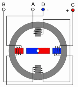
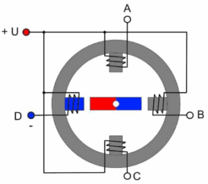
Now we remove the voltage from the winding AB and apply it to the winding CD (polarity + -). The current in the CD winding will cause a magnetic field with horizontal poles, left S, right N.
The magnetic field does everything so that the magnetic flux is closed along the minimum path. The rotor will turn to the position indicated in the figure. The mechanical position of the rotor is again stable. This was the first step of the motor. In our case, it is equal to one fourth of the turnover.
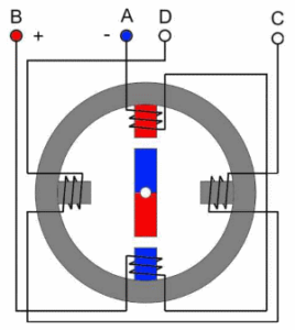
Turn off the CD winding and apply voltage again to the AB winding, but in a different polarity (- +). Again, the magnetic field of the stator will turn 90°, followed by the rotor.
One more commutation AB - disable, CD - connect (polarity - +) and the rotor makes another step on one-fourth of the circle.
The next commutation (which we started with) will return the rotor to its original position. We made a complete turn in 4 steps.
If you continue the phase switching, the rotor will rotate with a frequency proportional to the frequency of switching the phase windings.
If the phases are switched in the opposite sequence - spin in the opposite direction, stop switching - it will stop.
Bipolar and unipolar stepper motors
It was a bipolar stepper motor. The bipolar motor has one winding for each phase.
In the previous figures, these are windings AB and CD. To change the magnetic field, complex switching of the windings must be provided.
Each winding:
- disconnects from the voltage source;
- connects in straight polarity;
- connects with the opposite polarity.
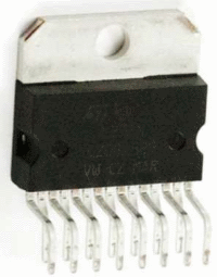
This type of switching requires a complex bridge driver. An example of such a device is the L298N chip.
The chip provides a switching current of up to 2 A. If large currents are needed, the task of controlling a bipolar motor is even more complicated.
There is another way to change the magnetic field in the stator with a much simpler switching scheme. This is the use of a motor with unipolar windings.
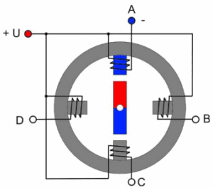
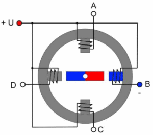
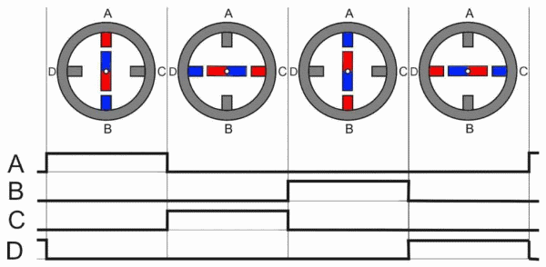
The circuit of a two-phase stepper motor with unipolar windings and the switching sequence of the windings looks like this.
For all four windings, one pin is connected to the positive terminal of the power source. And the other pins A, B, C, D are sequentially switched to the negative signal. The corresponding windings create a magnetic field, and the rotor turns after it.
To switch the windings in this way, four switches are enough to close the windings to the ground. The switches are often controlled directly from microcontroller pins.
Sometimes the middle terminals of the windings are structurally combined inside the motor, sometimes all the terminals are output separately. By the way, this is not a reason to call the motor four-phase. Anyway, it will be two-phase.
A bipolar motor provides, with the same dimensions, more torque than a unipolar one. It is understandable. At the same time, only one winding works in a unipolar motor, instead of two. The gain in torque for a bipolar is about 40%.
But, if there is no need to use the engine at full power, a unipolar motor is much easier to control.
Varieties of stepper motors
The main types of stepper motors:
- with variable magnetic resistance;
- with permanent magnets;
- hybrid.
Stepper motors with variable magnetic resistance
Motor with variable magnetic resistance do not have permanent magnets in the rotor. Its rotor is made of soft magnetic material and has a gear shape. The magnetic flux is closed through the teeth closest to the stator poles. The teeth are attracted to the poles. This ensures rotation.
With the same dimensions, motors with variable magnetic resistance have lower torque than other types of stepper motors.
They are used quite rarely. I know of only one company that has used such engines. I developed a controller for them. The choice of engines with variable magnetic resistance was due to the fact that the company itself produced all the engine parts. And it is much easier to make a rotor for this type of drive, because it does not use permanent magnets.
Permanent Magnet Motors
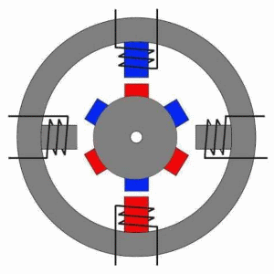
In stepper motors of this type, the rotor contains permanent magnets. I explained the general principle of operation of a stepper motor on a permanent magnet motor. Only in real motors there are more magnets. Here is an example of an engine with three pairs of rotor poles.
In real permanent magnet motors, the number of steps per revolution reaches 48, which corresponds to a step angle of 7.5 °.
Hybrid engines
Hybrid stepper motors provide a smaller step size, greater torque, and rotational speed. The number of steps per revolution for this type of engine reaches 400 (step angle 0.9 °).
But they are more complicated to manufacture and more expensive. I do not want to bother the reader with the design of these engines. They have both a gear rotor and permanent magnets. By the principle of operation, hybrid motors are equivalent to permanent magnet motors, but with a much larger number of poles.
This is the most common type of stepper motor.
Stepper motor control
There are three stepper motor control modes:
- full step;
- half step;
- microstepping.
The first method was described in the examples above. This is an alternating phase switching, the phases do not overlap, at each moment of time only one phase is connected to the voltage source. The method is called one phase on full step. The equilibrium points of the rotor coincide with the poles of the stator.
The disadvantage of this mode is that at the same moment half of the windings for the bipolar motor are used, and only a quarter for the unipolar motor.
There is a variant of full-step control mode in which two phases are enabled at the same time. It is called two-phase-on full step. With this method, the rotor is fixed between the poles of the stator due to the supply of power to all windings.
This allows you to increase engine torque by 40%. The step angle does not change, just the rotor in the state of equilibrium is shifted by half a step.
Half-step mode
This method allows the motor to get twice as many steps per revolution of the rotor. Every second step, one phase is turned on, and between them two are turned on at once.
As a result of such switching, the angular displacement of the step is reduced by half, or the number of steps is doubled. It is not possible to get the full moment in half-step mode. Despite this, half-step mode is often used. It doubles the number of engine steps using very simple methods.
It must be remembered that for both modes, it is true that when the motor is stopped with voltage removed from all phases, its rotor is in a free state and can be displaced from mechanical influences. To fix the position of the rotor, it is necessary to form a holding current in the motor windings. This current can be significantly less than the rated current.
The ability of the stepper motor to fix its position when stopped allows you to do without mechanical clamps, brake systems, etc.
Microstepping mode
To obtain an even greater number of engine steps, a microstepping mode is used. Switched on two phases, as in a half-step mode, but the currents of the windings are not evenly distributed.
The stator magnetic field is shifted between the poles, and the position of the rotor is shifted accordingly. As a rule, the disproportion of currents between the working phases occurs with a certain discreteness, microstep. There are micro-steps with a value of a quarter of the full step. There are much more. I was developing an inductor drive control system that had more than 1000 microsteps.
Microstep mode can significantly improve the positioning accuracy of the stepper motor. Although the drive control system is becoming much more complicated.
Disadvantages and advantages of stepper motors
Advantages of stepper motors.
- Precise positioning without feedback. The number of pulses determines the angle of rotation.
- The motor provides full torque when the rotation speed is reduced, up to a stop.
- The motor fixes its position when stopped due to the holding current.
- Adjustment of rotation speed with high accuracy without feedback.
- Ability to quickly start, stop, reverse.
- High reliability. No collector brushes.
Disadvantages of stepper motors
- Complex controlling system.
- Low rotational speeds.
- A resonance phenomenon is possible.
- Loss of positioning during mechanical overloads may occur.
- Low specific power.
Like everything else in the world, a stepper motor has certain advantages and disadvantages. But there are areas in precision mechanics in which it is irreplaceable. Where you need to move the mechanical components, instantly stop, move backward, adjust the speed ... Try to instantly stop the collector motor, and you will forget about the shortcomings of the stepper. Try to implement a change in the speed of the collector motor within a wide range. It is easier to use a stepper with its shortcomings.
In the packaging equipment that I developed, for example, the machine for filling and sealing ampoules contains 7 stepper motors, machine for filling loose preparations in ampoules contains 10 motors. And I can't replace any of these motors with a collector one. If you're interested, watch a movie about how stepper motors work in my equipment.
Characteristics and parameters of stepper motors
From the point of view of mechanics and electrical engineering, a stepper motor is a complex device that has many mechanical and electrical parameters. I’ll tell you about the main technical parameters that are used in practice.
The number of full steps per rotation. The main parameter of the engine, determining its accuracy, resolution, smoothness of movement. For FL57 series motors, this parameter is 200 and 400 steps per revolution.
Full step angle. Representation in another form of the previous parameter. Shows the angle at which the shaft will turn in one full step. It can be calculated as 360 ° / number of full steps per revolution. For motors of the FL57 series, it is 1.8 ° and 0.9 °.
Rated current. The main electrical parameter. The maximum permissible current at which the motor can operate for an arbitrarily long time. For this current, the mechanical parameters of the motor are specified.
Rated voltage. Permissible DC voltage on the motor winding in static mode. Often this parameter is not provided. It is calculated according to Ohm's law through the rated current and winding resistance.
Phase winding resistance. The resistance of the motor winding at a constant current. The parameter, together with the rated current, shows what voltage can be applied to the motor winding.
Phase inductance. The parameter becomes important at significant rotational speeds. The slew rate of the current in the winding depends on it. At high phase switching frequencies, it is necessary to increase the voltage so that the current increases faster.
Torque. The main mechanical parameter. Shows the maximum torque that the engine is able to create. Sometimes a mechanical characteristic is given as a function of torque versus speed.
Moment of inertia of the rotor. It characterizes the mechanical inertia of the motor rotor. The smaller this parameter, the faster the engine accelerates.
Holding moment. This is the torque with the engine stopped. In this case, the motor must be powered by two phases with rated current.
Locking moment. The moment needed to turn the motor shaft when there is no supply voltage.
Insulation resistance. As with all electrical appliances - the resistance between the housing and the windings.
Breakdown voltage. The minimum voltage at which breakdown of insulation occurs between the windings and the casing. Parameter from the electrical safety section.

