In the lesson we will learn about the diagrams for connecting seven-segment LED displays to microcontrollers, about how to control them.
Previous lesson List of lessons Next lesson
LED seven-segment indicators remain one of the most popular elements for displaying digital information.
The following qualities contribute to this.
- Low price. In the display devices there is nothing cheaper than LED digital displays.
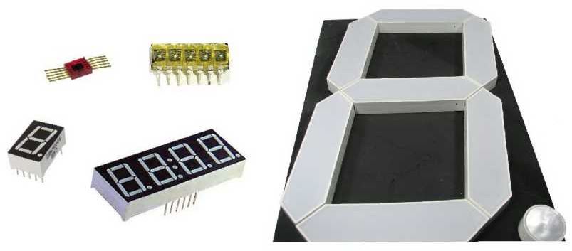
- Variety of sizes. The smallest and largest displays - LED. I am aware of LED indicators with the digit hight from 2.5 mm to 32 cm.
- They glow in the dark. In some applications, this property is almost decisive.
- LED displays have a different glow colors. There are even two-color.
- They have sufficiently small control currents. Modern LED displays can be connected to the pins of microcontrollers without additional switches.
- LED displays allow harsh operating conditions (temperature range, high humidity, vibrations, aggressive media, etc.). For this quality, they have no equal among other types of display elements.
- Unlimited service life.
Types of LED displays.
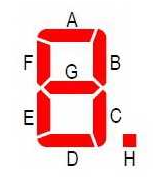
Seven-segment LED indicator displays the symbol using seven LEDs - digit segments. The eighth LED shows the decimal point. So the seven-segment display has 8 segments.
The segments are denoted by Latin letters from ”A” to ”H”.
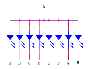
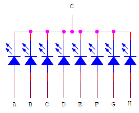
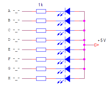
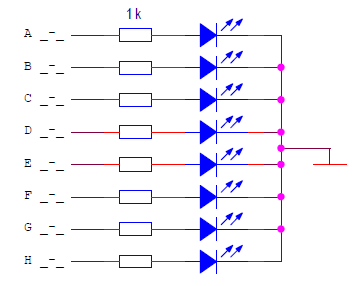
The anodes or cathodes of each LED are combined in the display and form a common wire. Therefore, there are common anode and common cathode displays.
A common anode LED display.
A common cathode LED display.
Static LED control.
It is necessary to connect LED displays to the microcontroller through current-limiting resistors.
The calculation of the resistors is the same as for individual LEDs.
R = (U power - U segment) / I segment
For this scheme: I segment = (5 - 1.5) / 1000 = 3.5 mA
Modern LED indicators glow quite brightly already at a current of 1 mA. For a circuit with a common anode, the segments will light up, on the control outputs of which the microcontroller will form a low level.
In the connection circuit of a common cathode display, the polarity of the power supply and control signals changes.
The segment will be illuminated, on the control output of which a high level will be formed (5 V).
Multiplexed control mode of LED displays (dynamic indication).
To connect each seven-segment indicator to the microcontroller, eight pins are required. If you need to connect 3 - 4 displays (digits), then the task becomes practically impossible. Just not enough pins of the microcontroller. In this case, the indicators can be connected in multiplexed mode, in the dynamic display mode.
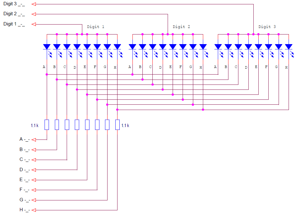
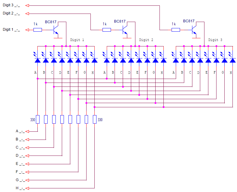
It is necessary to connect the same segments of each display digit. It turns out a matrix of LEDs connected between the pins of the segments and the common pins of the indicators.
Here is a multiplexed control circuit for a three-digit common anode display.
To connect the three digits display to the controller, it took 11 pins, not 24, as in the static control mode.
With dynamic display, only one digit is lit at a time. A high level signal (5 V) is sent to the common pin of one of the digits, and low level signals are sent to the segment pins for those segments that should be lit in this digit. After a certain time, the next digit comes on. A high level is formed on its common pin, and state signals for this digit are sent to the segment pins. And so for all digits in an infinite loop. The cycle time is called the display regeneration time. If the regeneration time is short enough, then the human eye will not notice the switching of digits. It will seem that all digits are lit constantly. To eliminate flickering of display digits, it is considered that the frequency of the regeneration cycle should be at least 70 Hz. I try to use at least 100 Hz.
A dynamic indication circuit for a common cathode LED display looks like this.
The polarity of all signals changes. Now a low level is supplied to the common wire of the active digit, and a high level is supplied to the segments that should be lit.
Calculation of elements for dynamic LED displays.
The calculation is somewhat more complicated than for the static mode. During the calculation it is necessary to determine:
- average segment current;
- pulse segment current;
- resistance of segment resistors;
- pulse current of common pins of digits.
Since LEDs light up in turn, then the brightness of the glow determines the average current. We must choose it based on the parameters of the indicator and the required brightness. The average current will determine the brightness of the indicator at a level corresponding to the static control with the same constant current.
Let's choose the average segment current 1 mA.
Now we calculate the pulse current of the segment. To provide the required average current, the pulse current must be N times greater. Where N is the number of digits of the display.
I segment pulse = I segmeny average * N
For our scheme I segment pulse = 1 * 3 = 3 mA.
Calculate the resistance of the current limiting resistors.
R = (U power - U segment) / I segment pulse
R = (5 - 1.5) / 0.003 = 1166 Ohm
We determine the pulse currents of the common pins of the digits. At the same time, 8 segments can be lit, which means that the pulse current of one segment should be multiplied by 8.
I digit pulse = I segment pulse * 8
For our scheme I digit pulse = 3 * 8 = 24 mA.
Eventually:
- resistance of resistors choose 1.1 kΩ;
- the microcontroller pins for the segments control must provide a current of at least 3 mA;
- the microcontroller pins for the selection of the digits should provide a current of at least 24 mA.
With such values of the currents, the display can be connected directly to the Arduino board pins, without using additional switches. For bright displays, such currents are enough.
Circuits with additional switches.
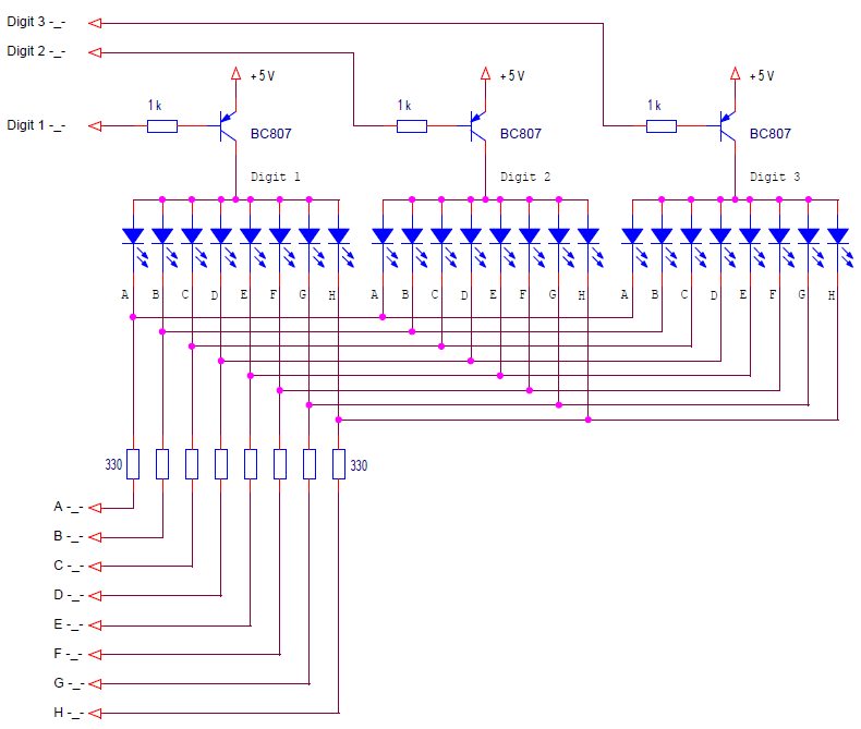
If the displays require more current, then additional switches must be used, especially for the common signals of digits. The total current of a digit is 8 times the current of one segment.
Here is a multiplexed control circuit for a common anode LED display with transistor switches of digits selecting.
To select a digit in this circuit it is necessary to form a low level signal. The corresponding switch will open and energize the digit pin.
A multiplexed control circuit for a common cathode LED display with transistor switches of digits selecting.
To select a digit in this circuit, it is necessary to form a high level signal. The corresponding switch will open and close the common pin of the digit to the ground.
There may be circuits in which it is necessary to use transistor switches for both segment pins and common digit pins. Such schemes are easily synthesized from the previous two. All shown circuits are used when powering the display with voltage equal to the power supply of the microcontroller.
Switches for indicators with high voltage supply.
There are indicators of large sizes, in which each segment consists of several LEDs connected in series. To power such indicators, a source with a voltage greater than 5 V is required. The switches must provide overvoltage switching with control from the signals of the microcontroller levels (usually 5 V).
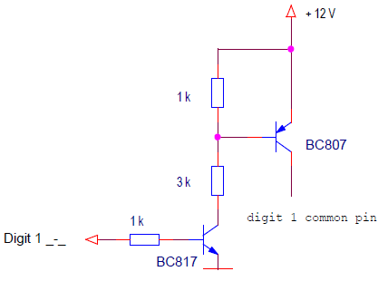
The scheme of the swithes closing the indicator signals to the earth remains unchanged. And the power switches should be based on a different scheme, for example, such.
In this scheme, the active digit is selected by a high level of the control signal.
Between switching the digits of the display for a short time (1-5 μs) all segments should be turned off. This time is needed to complete the switching transients.
Structurally, the pins of the digits can be combined in one case of a multi-digit display, and a multi-digit display can be assembled from individual single-digit ones. Moreover, you can collect a display from individual LEDs, combined into segments. This is usually done when it is necessary to assemble a very large indicator. All the above schemes will be valid for such options.
In the next lesson, we'll connect a seven-segment LED display to the Arduino board, develop a library for controlling it.

