In the lesson, we will connect the STEP/DIR driver TB6560-V2 to the Arduino board and learn how to control it using the StepDirDriver library.
Previous lesson List of lessons Next lesson
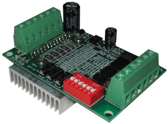
TB6560-V2 is an inexpensive stepper motor driver that supports all typical STEP/DIR driver modes and functions.
In the lesson, we will control it using the Arduino board. All circuits and lesson programs will be suitable for any other STEP/DIR driver.
Connecting the driver to the Arduino board.
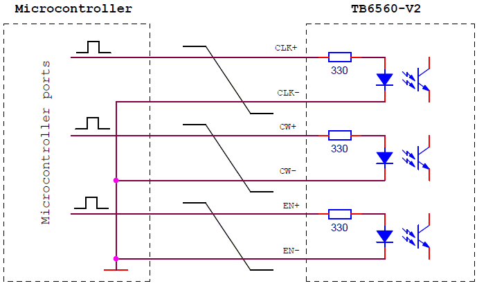
In the article about the TB6560-V2 module, there are two wiring diagrams for the microcontroller. We will use this one.
When the signal level is high (+5 V), current flows through the LED of the input optocoupler, and the module perceives this as an active control level. The 330 ohm resistors limit the LEDs current. Those, the driver can be controled by signals directly from the microcontroller pins.
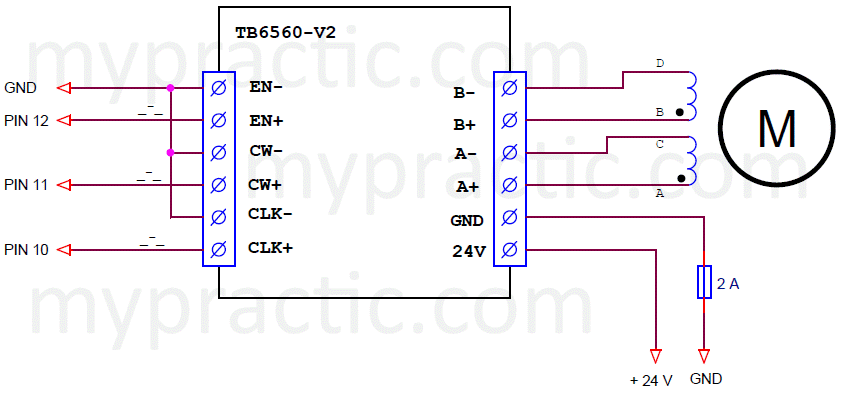
With this in mind, the complete diagram for connecting the TB6560-V2 driver to the Arduino board looks like this.
Pay attention to the fuse. I highly recommend installing it in the device. In circuits with simple drivers, when the switches fail, an operating current flows through the motor, limited either by the resistance of the winding or by an additional resistor. In drivers with current stabilization, the current is regulated by PWM modulation. If the output switches fail in such devices, then the full supply voltage can be applied to the motor. This will lead to unacceptable current and failure of the stepper motor. This process is slow, therefore any fuse - fusible or self-restoring - will save from failure of the motor.
The driver parameters are set by switches on the module board. I set the phase current to 1 A.
DIP-switches S3 and S4 select the phase switching mode.
| DIP-switches state |
Mode |
|
| S3 | S4 | |
| OFF | OFF | full-step |
| ON | OFF | half-step |
| ON | ON | microstepping 1/8 step |
| OFF | ON | microstepping 1/16 step |
To begin with, I set full-step mode, then tested all the others. The modes are described in the article about the TB6560-V2 module. It also shows how to set them using the module DIP-switches.
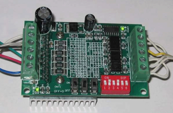
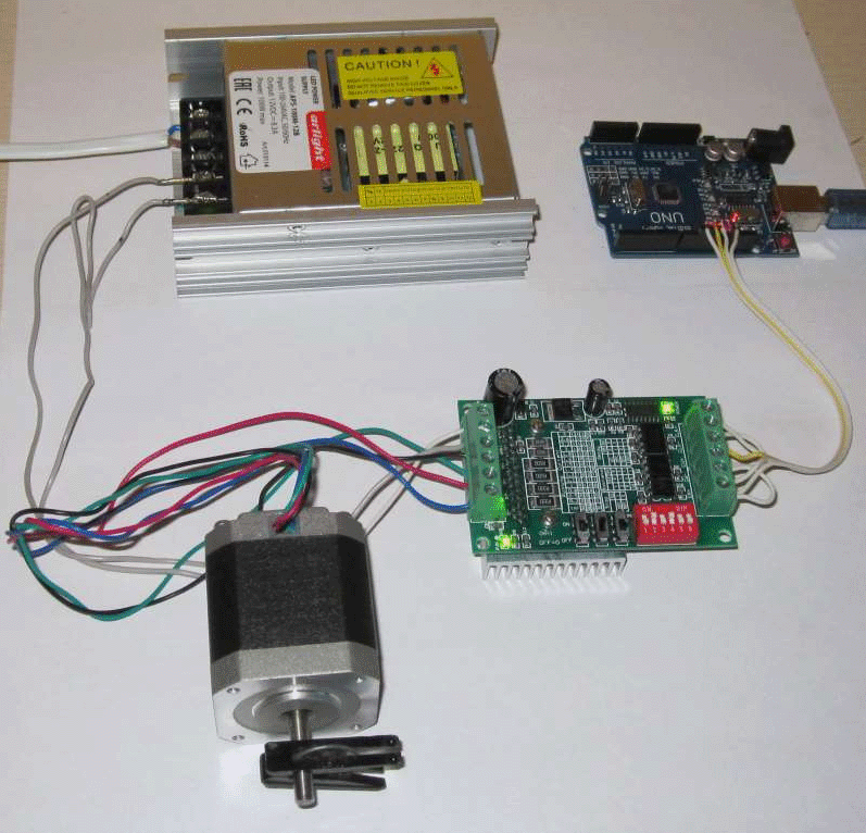
The assembled circuit looks like this.
It remains to learn how to control such a system.
The StepDirDriver library.
I developed this library to control STEP/DIR drivers. It is fully functionally compatible with the StepMotor library (lesson 29). Only 2 differences:
- The constructor has other arguments. It's just that the STEP/DIR driver requires different control signals and a different number of signals.
- In the mode setting function setMode(), the stepMode parameter (switching mode) is ignored. The mode is set by DIP-switches of the driver.
You can download the StepDirDriver library from this link.
Description of the StepDirDriver class.
The class has the following public methods.
class StepDirDriver {
public:
StepDirDriver(byte pinStep, byte pinDir, byte pinEn); // constructor
void control(); // control, the function must be called regularly with the maximum phase switching frequency
void step(int steps); // initiates rotation of the rotor by the specified number of steps
void setMode(byte stepMode, boolean fixStop); // sets the phase switching and stop modes
void setDivider(int divider); // setting a frequency divider for switching phases
int readSteps(); // read remaining steps
} ;
It is not difficult to guess about the purpose of the constructor arguments:
- pinStep - output of the STEP signal;
- pinDir - output of the DIR signal;
- pinEn - output of the ENABLE signal.
StepDirDriver myMotor1(10, 11, 12); // create a StepDirDriver object, set pins for STEP, DIR, ENABLE signals
Description of the StepDirDriver library methods.
void control()
The method must be called regularly in a parallel process (timer interrupt). It generates control signals that determine the phase commutation. The frequency with which the control () function is called together with the divider set by the setDivider function determines the speed of rotation of the motor.
// interrupt handler 200 μs
void timerInt () {
myMotor1.control(); // motor control
}
void step(int steps)
The method initiates the rotation of the motor by the specified number of steps. In microstepping modes, we are not talking about physical steps of the motor, but about microsteps. The steps parameter with a positive value initiates a counterclockwise rotation, a negative value initiates a clockwise rotation.
By starting the rotation with the function step()
myMotor1.step(300); // to make 300 steps counterclockwise
the program can perform other tasks. The motor will stop by itself.
The engine can be stopped at any time with the command
myMotor1.step(0); // to stop motor
Nothing prevents you from setting a new number of steps without waiting for the motor to stop. For continuous rotation, you can periodically call the step() function with a large number of steps.
myMotor1.step(30000); // permanent rotation
You can find out that the motor has stopped using the readSteps() method.
void setMode(byte stepMode, boolean fixStop)
The method sets the state of the motor when stopped.
- If fixStop = true, when stopped, the holding current is applied to the motor windings, the rotor position is fixed.
- With fixStop = false, the voltage is removed from the motor windings when stopped.
The stepMode argument is ignored. It was added for compatibility with the same function of the StepMotor library.
myMotor1.setMode(0, true); // fix the rotor when stopping
myMotor1.setMode(0, false); // the motor is completely disabled
void setDivider(int divider)
The function sets the frequency division coefficient of the control() method call, which means it determines the engine rotation speed.
The rotation speed can be calculated using the following formula:
Rpm = 60,000 / (divider * Tcontrol * Nmotor) / Nmicrosteps
- Rpm - rotation speed in revolutions per minute;
- Tcontrol - period of calling the control () method in ms;
- Nmotor - the number of motor steps per full revolution;
- Nmicrosteps - the number of motor microsteps per phase.
For full-step mode Nmicrosteps = 1, for a half-step mode Nmicrosteps = 2, etc.
myMotor1.setDivider (8); // frequency divider 8
int readSteps ()
The method reads the number of steps remaining before the motor stops. Returning 0 means that the engine is stopped.
if (myMoto1r.readSteps() == 0) {
// engine stopped
}
Examples of using the StepDirDriver library.
Using the new library is no different from using the StepMotor library functions from the previous lessons.
There are only two differences:
- Including the library #include <StepDirDriver.h> instead of #include <StepMotor.h>.
- Another format of the constructor StepDirDriver myMotor (10, 11, 12); instead of StepMotor myMotor (10, 11, 12, 13).
Only 2 lines change in the program.
Here is a sketch from lesson 29 modified for the new library (sketch_35_1).
It forces the engine to make 2 turns clockwise at a speed of 1 revolution per second, then pause for 1 second, 2 turns counterclockwise, pause again for a second and so on in a cycle.
// stepper motor control program using StepDirDriver library
// the motor makes 2 revolutions counterclockwise,
// then a pause of 1 second, another 2 turns clockwise,
// pause 1 second, and so on in an infinite loop
#include <TimerOne.h>
#include <StepDirDriver.h>
StepDirDriver myMotor(10, 11, 12); // create an object of type StepDirDriver, set pins for the signals
unsigned int timeCounter; // time counter
byte md; // mode: 0 - rotation counterclockwise, 1 - pause, 2 - rotation clockwise, 3 - pause
void setup() {
Timer1.initialize(250); // set the timer interrupt period to 250 mks
Timer1.attachInterrupt(timerInterrupt, 250);
myMotor.setMode(0, false); // step mode, without fixing when stopped
myMotor.setDivider(20); // frequency divider 20 (when interrupting 0.25 ms, the phase switching period is 5 ms)
md= 0; // initial mode
myMotor.step(400); // initial start
}
void loop() {
// control motor rotation
if (md == 0) {
// 2 turns counterclockwise
if (myMotor.readSteps() == 0) { md=1; timeCounter=0; }
}
else if (md == 1) {
// pause 1 sec
if (timeCounter >= 4000) { md=2; myMotor.step(-400); }
}
else if (md == 2) {
// 2 turns clockwise
if (myMotor.readSteps() == 0) { md=3; timeCounter=0; }
}
else {
// pause 1 sec
if (timeCounter >= 4000) { md=0; myMotor.step(400); }
}
}
//-------------------------------------- 0.25 ms interrupt handler
void timerInterrupt() {
myMotor.control(); // motor control
timeCounter++; // time counter
}
Don't forget to install the StepDirDriver library.
Testing the stepper motor driver with AT commands.
I replaced two lines of the computer-controlled driver program from Lesson 31 and got a new device for working with a stepper motor.
You can download the new AT command driver from this link.
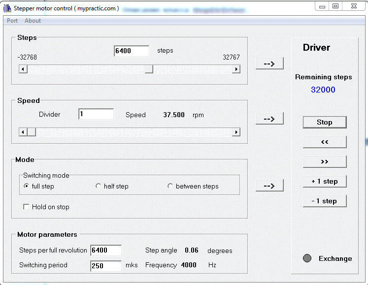
I assembled the system according to the scheme at the beginning of the lesson and tested it in various modes. I will not describe everything in detail. I will focus on the microstepping mode.
I set microstepping mode with 16 microsteps. My motor has 400 physical steps. In microstepping mode, the result is a motor that has as many as 6400 steps per revolution! I tried to control the top-level program StepMotor (lesson 31).
Everything works. The rotor positioning accuracy is incredible.
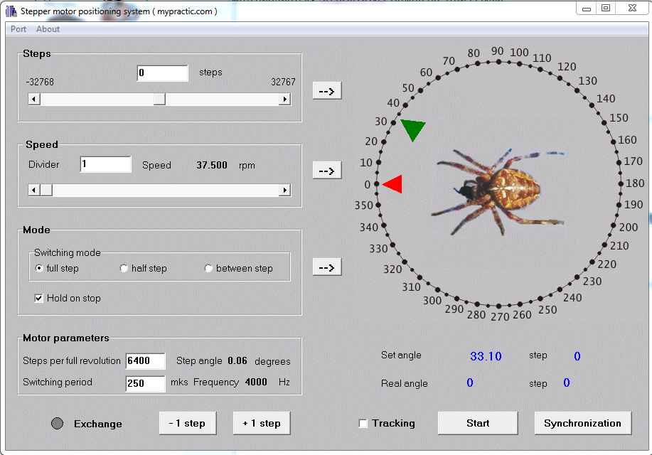
I also checked the operation of the positioning system from lesson 32.
The rotor position resolution is almost 0.05 °!
I think in the last two lessons I convincingly showed the advantages of STEP/DIR drivers. But which driver to use in a particular case is up to the developer. What is more important is the low price of a simple switch driver or the functionality of a STEP/DIR driver.
It is necessary to choose the best option. In some cases, you cannot do without a STEP/DIR driver; in other projects, simple drivers will work quite well.

