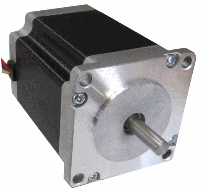
Using the L298N driver, we will connect a bipolar stepper motor to the Arduino board. For control, we will use the programs from the previous lessons for unipolar motors.
Previous lesson List of lessons Next lesson
Using stepper motors in bipolar mode gives:
- Increase in torque by about 40% compared to a unipolar motor.
- Allows the use of motors with any configuration of phase windings.
The disadvantage of bipolar mode is the more complex driver.
Bipolar stepper motor driver.
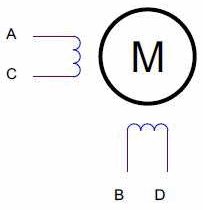
A bipolar stepper motor has two windings, one for each phase.
If 4 switches are enough to control a unipolar motor, which close the terminals of the windings to ground, then a bipolar drive requires more complex switching of the windings. Each winding is required:
- connect to power supply in direct polarity;
- disable;
- connect to source in opposite polarity.
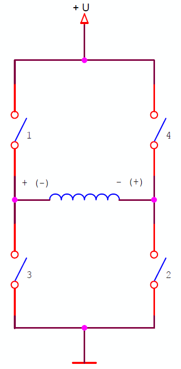
Such switching can be provided by a bridge circuit with four switches.
When switches 1 and 2 are closed, the supply voltage is applied to the winding in the forward direction. Closing switches 3 and 4 connects the power supply in reverse polarity.
A bipolar stepper motor driver is much more complex than a unipolar stepper motor driver.
- Requires 4 switches per winding, ie. 8 switches per motor.
- Complex circuits for controlling the upper switches (switches 1, 4) from the logic signals of the microcontroller, “tied” to the ground, are required.
- There is a problem with through currents. They occur when transistors from one arm are simultaneously turned on (through current 1, 3 or 2, 4). This can lead to a short circuit of the power supply and burnout of the switches.
- Through currents can appear due to the unequal speed of the upper and lower switches. For example, the upper key has already closed, and the lower one has not had time to disconnect.
Therefore, it is rather difficult to implement a powerful bipolar stepper motor driver circuit using discrete elements. It is much more practical, more convenient, cheaper to use an integrated driver.
L298N bipolar stepper motor driver.
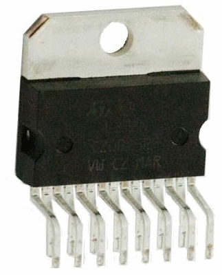
The L298 is probably the most common bipolar driver.
This is a full bridge driver that allows you to control bipolar loads with a current of up to 2 A and a maximum voltage of 46 V. A detailed description of the L298N microcircuit can be viewed at this link.
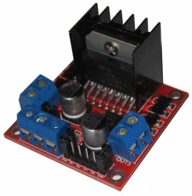
The L298N module was developed on the basis of the L298N chip.
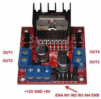
Structurally, it is made on one board with dimensions of 43 x 43 mm. The board contains:
- L298N chip with a cooling radiator;
- terminal blocks for connecting power supply and load;
- connector for connecting control signals;
- voltage stabilizer 5 V;
- protective diodes.
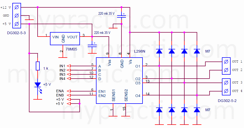
Schematic diagram of the L298N module.
The L298N chip is used according to the standard scheme.
The diodes protect the switches from emissions when switching windings. Through them, the energy stored in the inductance of the windings is discharged.
The module contains a + 5 V voltage regulator for powering the logic part of the chip. The +5 V voltage is generated from the motor supply voltage. On the terminal block, it is marked +12 V, but it can vary within a wide range of 8 ... 46 V.
The half-bridges are controlled from the input signals IN1, ..., IN4. Signal levels 0/5 V. At a low level, the output is connected to ground, at a high level - to the motor power supply (+12 V).
The maximum permissible current of the phase is 2 A. There is no current protection in the module. But the implementation of overcurrent protection significantly complicates the circuit, and a short circuit of the motor windings is an unlikely event. I have not met with such. In addition, mechanical blocking of the stepper shaft does not cause an overcurrent.
Connecting a bipolar motor to the Arduino board.
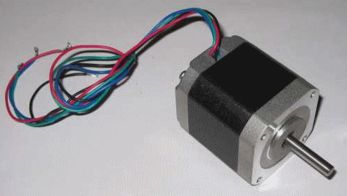
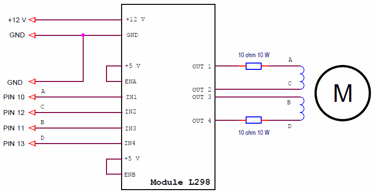
I connected a FL42STH47-1684 motor to the board. It is a 4-lead bipolar stepper motor with 1.68 A phase current and 1.65 ohm winding resistance.
I have a power supply of 12 V. If the motor is connected directly through the switches, then the current in the windings will be 12 V / 1.65 A = 7 A. The engine will burn out. Therefore, I connected limiting resistors in series with each winding. The diagram looks like this.
I used 10 ohm resistors. The phase current can be calculated using the formula:
Iphase = (Upower - Uswitch) / (Rlimit + Rwinding)
- Iphase - phase current.
- Upower - the voltage of the power supply, I have 12 V.
- Uswitch - voltage drop across the closed keys of the driver. For the L298, this is the sum of the drops on the upper (Source Saturation Voltage) and lower switches (Sink Saturation Voltage). From the reference data, we determine that 2-2.5 V drops on the switches of the L298N driver.
- Rlimit - resistance of limiting resistors. My circuit has 10 ohms.
- Rwinding - resistance of motor windings. The FL42STH47-1684 motor has a resistance of 1.65 ohms.
As a result, for my circuit, the phase current will be:
Iphase = (12 - 2) / (10 + 1.65) = 0.86 A.
Significant power can be generated across the limiting resistors. In my circuit, 0.86 * 0.86 * 10 = 7.4 watts. I used 10W resistors.
It is possible to connect a motor without limiting resistors by reducing the supply voltage. But in a circuit with resistors, the drive will rotate at a higher speed due to the fact that the phase currents increase faster.
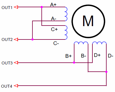
There are different options for bipolar motors. I will list the main ones and show the connection diagrams.
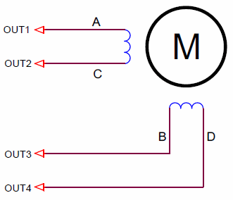
4-lead motor.
This is the most common scheme.
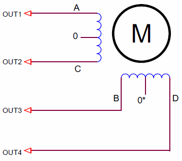
6-lead motor.
It must be remembered that the resistance of the windings is added and in order to provide the same phase current as for the unipolar mode, it is necessary to double the driver supply voltage.
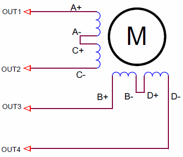
Motor with 8 pins, serial connection of windings.
The resistances of the windings add up, and twice the supply voltage is required.
8-lead motor, parallel winding.
The windings are connected in parallel. The total resistance is two times less, the current, at the same supply voltage, is twice the motor current. But the total inductance decreases, which means that the rate of rise of the current in the windings increases.
Testing the operation of the device.
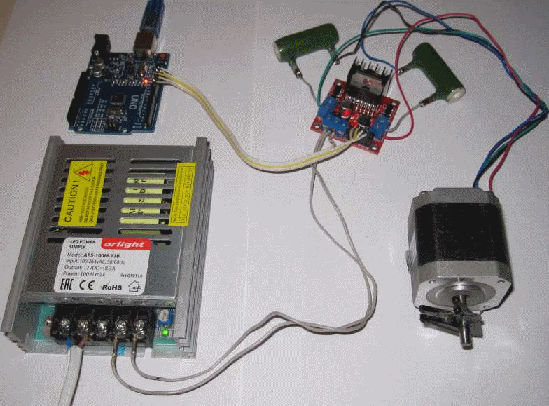
My version of the assembled circuit looks like this.
We will not develop any programs in this lesson. All programs from lessons 28, 29, 31, 32 should work without changes. Just pay attention to the sequence of connecting the control signals of the L298N module to the pins of the Arduino board. The outputs of phases A, B, C, D for the unipolar motor correspond to the control outputs IN1, IN3, IN2, IN4 of the L298N module.
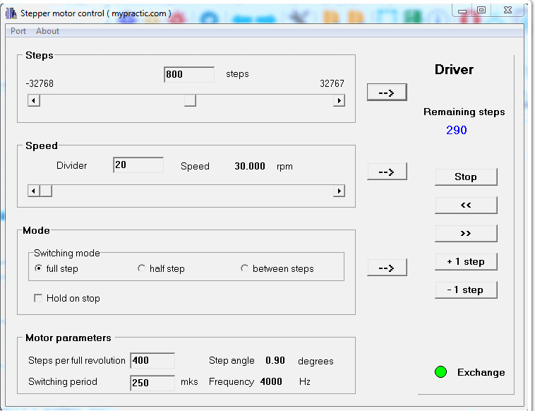
First, I loaded the driver program into the Arduino board with control from the computer via the AT command protocol and tested the work with the top-level StepMotor program. The resident program (for the Arduino board) and the top-level program (for the computer) can be taken from lesson 31.
Everything is working. The rotation speed of my motor, included in this scheme, reaches 150 rpm. The unipolar motor FL57STH76-1006 in the previous lessons rotated at a speed of no more than 60 rpm. An increase in the speed of rotation of the motor by 2.5 times is associated, first of all, with a higher rate of rise of currents in the windings. This is due to the lower inductance of the windings and the use of a circuit with limiting resistors. To be convincing, I will calculate the rate of current rise for both drives.
For the motor from previous lessons (FL57STH76-1006):
- winding inductance 14 mH;
- when powered by 12V, the current in the winding reaches 1 A per time T = I * L / U = 1 A * 14 mH / 12V = 1.2 ms.
For the motor I used in this tutorial (FL42STH47-1684):
- winding inductance 3.2 mH;
- when powered by 12V, the current in the winding reaches 1 A per time T = I * L / U = 1 A * 3.2 mH / 12V = 0.3 ms.
Hence the increase in rotation speed. Of course, this was also influenced by:
- increase in torque due to bipolar switching mode;
- other moment of inertia of the rotor;
- lower phase current;
- the number of motor steps per revolution significantly affects, but for me this parameter is the same for both motors.
But if the current does not have time to grow to the desired value during the phase turn-on, then everything else is no longer so important.
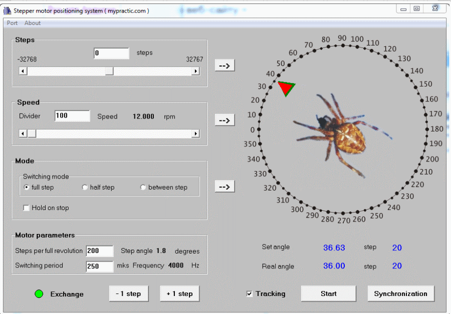
Then I checked the operation of the positioning system with a new motor. The resident program of the Arduino board remains the same. And for control from a computer, I used the Tracker program from lesson 32.
The positioning system began to work much faster. I shot a short video of the stepper motor positioning system in full-step and half-step modes.
The motor shaft follows the pointer on the computer monitor clearly faster.
In this lesson, I tried not only to tell you how to work with unipolar stepper motors, but also to show the effect of the rate of rise of the current in the phase windings on the speed of rotation of the motor.
In the next tutorial I will show you how to work with STEP/DIR stepper motor drivers. I will present a library for controlling such devices.

