A series of articles about temperature measurement using Arduino controllers would be incomplete without a story about thermocouples. Moreover, there is nothing else to measure high temperatures.
Previous lesson List of lessons Next lesson
Thermocouples (thermoelectric transducers).
All thermal sensors from the previous lessons allowed to measure the temperature in the range no wider than-55 ... + 150 °C.To measure higher temperatures, the most common sensors are thermocouples. They:
- have an extremely wide temperature measurement range -250 ... + 2500 °C;
- can be calibrated for high measurement accuracy, to an error of not more than 0.01 ° C;
- usually have a low price;
- are considered reliable temperature sensors.
The main disadvantage of thermocouples is the need for a fairly complex precision meter, which should provide:
- measurement of low values of voltage (thermo-electromotive force) with an upper value of the range of tens, and sometimes even units of mV;
- compensation of thermoelectric force of the cold junction;
- linearization of thermocouple characteristics.
The operating principle of the thermocouple.
The operating principle of this type sensors is based on the thermoelectric effect (Seebeck effect). Therefore, another name for a thermocouple is thermoelectric transducer.
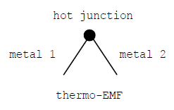
A potential difference is formed in the chain between the connected dissimilar metals. Its value depends on the temperature. Therefore, it is called thermoelectric voltage or thermo-electromotive force (thermo-EMF). For different materials, the value of thermo-EMF is different.
If the joints (junctions) of dissimilar conductors in the circuit are connected into a ring and have the same temperature, then the sum of the thermoelectric voltages is zero. If the wire junctions are at different temperatures, the total potential difference between them depends on the temperature difference. As a result, we come to the thermocouple construction.
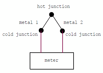
Two dissimilar metals 1 and 2 at one point form a working junction. It is also called a hot or measuring junction. The hot junction is placed at a point whose temperature must be measured.
Cold junctions are the connection points of thermocouple metals to another metal, usually copper. It can be terminal blocks of the measuring device or copper wires of communication with the thermocouple. In any case, it is necessary to measure the temperature of the cold junction and take it into account in the calculations of the measured temperature.
The most common types of thermocouples.
The most widely used thermocouples are type K (chromel - copel) and type L (chromel - alumel).
| Type | Materials | Measuring range, °C | Sensitivity, μV / ° C, (at temperature, ° C) |
Thermo-EMF, mV, at 100 ° C |
| L | Chromel, kopel | - 200 … + 800 | 64 (0) 88 (600) |
6,86 |
| K | Chromel, alumel | - 270 … +1372 | 35 (0) 42 (1300) |
4,10 |
How to practically measure temperature with a thermocouple. Measurement method.
The nominal static characteristic (NSC) of the thermocouple is given in the form of a table with two columns: the temperature of the working junction and the corresponding thermo-EMF.
Here is a reference table for the K-type thermocouple with a voltage value through each degree: thermocouple_K_reference_table.pdf.
I used the Russian document: GOST R 8.585-2001.pdf.
To measure temperature using a thermocouple, you must perform the following steps:
- to measure the thermo-EMF (voltage) of the thermocouple (E total);
- to measure the cold junction temperature (T cold junction);
- to determine the cold junction thermo-EMF (E cold junction) using the cold junction temperature of the thermocouple according to the NSC table;
- determine the thermo-EMF of the hot junction, ie add the cold junction EMF to the total thermo-EMF (E hot junction = E total + E cold junction);
- according to the NSC table, determine the temperature of the hot junction using the thermo-EMF of the hot junction.
Here's an example of how I measured the temperature of a soldering iron tip with a K-type thermocouple.
- I touched the working junction to the soldering iron tip, measured the voltage at the terminals of the thermocouple. It turned out 10.6 mV.
- Ambient temperature, ie the cold junction temperature is approximately 25 ° C. The thermo-EMF of the cold junction from the reference table at 25 ° C is 1 mV.
- Thermo-EMF of the hot junction is 10.6 + 1 = 11.6 mV.
- The temperature from the same table for 11.6 mV is 285 ° C. This is the measured value.
This sequence of actions we need to implement in the Arduino thermometer program.
Arduino thermometer for measuring high temperatures using thermocouple type K.
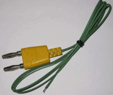
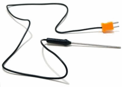
I found a TP-01A thermocouple. Typical, widespread K-type thermocouple for a multimeter. I will use it.
The package contains the following parameters:
- type K;
- measuring range - 60 ... + 400 ° C;
- accuracy ± 2.5% in the range up to 400 ° C.
The measuring range is for fiberglass cable. There is a similar thermocouple TP-02, but with a probe 10 cm long.
TP-02 has an upper limit of 700 ° C. So, we will develop a thermometer:
- for thermocouple type K;
- with a measuring range of 60 ... + 700 ° C.
Having understood the program and device diagram, you can create a meter for thermocouples of any type with any measuring range.
The remaining functionality of the thermometer is the same as that of the devices from the previous three lessons, including the function of recording temperature changes.
Arduino thermometer circuit diagram for a thermocouple.
We must connect to the Arduino board:
- seven-segment LED display;
- cold junction temperature sensor, I used TMP36;
- thermocouple.
We connected the first two elements in previous lessons about temperature measurement. But to connect a thermocouple to the Arduino board, you need to develop a precision amplifier. Not a very simple task.
Circuit diagram of a measuring amplifier for a thermocouple.
Let's form the requirements for the amplifier.
- Input voltage range - 2.24 ... + 29.13 mV. These are the extreme values of thermo-EMF for our measuring range (–60 ... + 700 ° C). Taken from the refsrence table for a type K thermocouple. But this is for the cold junction temperature of 0 ° C. We expand the range by another 2 mV, taking into account the maximum temperature of the cold junction + 40 ° C. As a result, for a K type thermocouple:
| Thermocouple type | K |
| Measuring temperature range | –60 … + 700 °C |
| Cold junction temperature range | 0 … + 40 °C |
| Input voltage range | - 4,3 … + 30 mV |
- The range of the output voltage of the amplifier is 0 ... 1.1 V. Obviously, in order for the gain to be less, we select the minimum reference voltage of the ADC, i.e. 1.1 V.
- Gain 1100 / (4.3 + 30) = 32, offset for measuring negative voltage + 4.3 mV.
| Output voltage | 0 … 1100 mV |
| Gain | 32 |
| Смещение | + 4,3 mV |
These parameters need to be somewhat expanded so that there is a margin for errors of the amplifier elements. We will compensate all errors in the program.
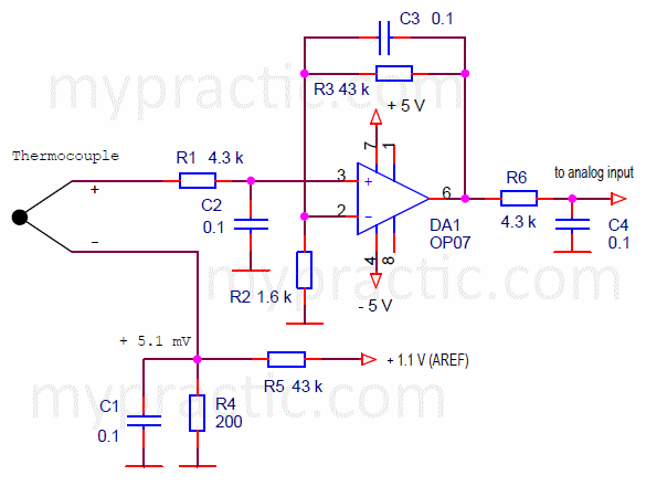
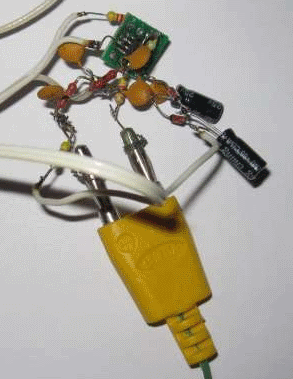
Now directly about the circuit of the measuring amplifier. I built it according to the scheme of a non-inverting amplifier based on an operational amplifier . I chose OP07 device. It is a precision operational amplifier with low bias voltage, low input current, high gain.
In this regard, I completely abandoned analog adjustments, i.e. using trimming resistors, and replaced them with program coefficients.
The amplifier circuit diagram for a thermocouple looks like this.
The gain is set by resistors R2 and R3.
K = R3 / R2 + 1
I chose K = 43 / 1.6 + 1 = 27.875.
Resistors R4 and R5 set the offset + 5.1 mV, which is necessary for measuring temperatures below 0. The thermocouple voltage in this case is negative and in order to measure it with a unipolar ADC, it is necessary to shift it in the positive side. The offset will be taken into account in the program.
The capacitors provide analog filtering of interference. At such low signal levels, this is absolutely necessary. Additionally, the program implements digital filtering of the signal.
In order for the amplifier to work at output voltages close to zero, it is necessary to provide bipolar power supply to the operational amplifier. There is no desire to connect an additional power supply to the device. Negative supply voltage can be obtained from the Arduino board using the following simple circuit.
A signal is generated on the digital output of the Arduino board with a meander shape and logic levels of 0 and 5 V. You can generate it using hardware PWM, but we will do it programmatically. In the interrupt handler from the timer with a period of 2 ms, we put the command to invert the output state. . This will produce a rectangular signal with a period of 4 ms.
- When the signal level is high, the capacitor C8 is charged by the circuit: microcontroller output, resistor R8, diode VD1.
- At low level it discharges to capacitor C9 by the circuit: microcontroller output, resistor R8, diode VD2.
- As a result, a voltage of approximately –4 V is generated on the capacitor C9.
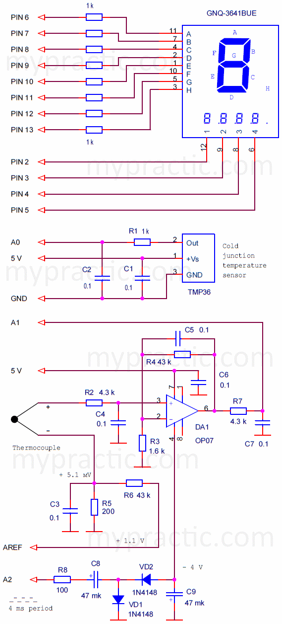
The complete circuit diagram of an Arduino thermometer for a thermocouple looks like this.
As resistors R3, R4, R5, R6, it is desirable to use accurate, thermostable elements. I used ordinary resistors with 5% accuracy. I pre-measured their real resistance and took this into account in the program.
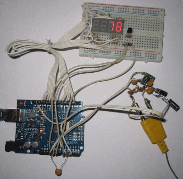
To debug the program and verify the operation of the device, I assembled it on a breadboard.
I assembled the measuring amplifier as a separate unit. On a solderless breadboard it would hardly work. All connections of the components should be of minimum length and securely soldered.
The resident program of the Arduino thermometer for thermocouples.
The software of the device differs from the thermometer programs from the three previous lessons only in the thermocouple junction temperature calculation unit. I will not give the entire program of the thermometer in the article. I will show only software modules for processing thermocouple data.
The fully resident thermocouple thermometer program can be downloaded here: sketch_27_1.zip.
The program uses MsTimer2 and Led4Digits libraries.
I recall the sequence of actions that must be performed in the program:
- measure the thermo-EMF at the terminals of the thermocouple;
- measure the temperature of the cold junction;
- determine the thermo-EMF of the cold junction according to the reference table of thermocouple;
- determine the thermo-EMF of the working junction, ie add the cold junction EMF to the total thermo-EMF;
- determine the temperature of the working junction using the thermo-EMF of the working junction according to the reference table of the thermocouple.
First of all, the program should have a table of the nominal static characteristic (NSC) of the thermocouple. We take it from the reference table for K-type thermocouple. In the document, it is specified for each degree.
We need a part of the table from - 60 to + 700 ° C. The array of thermo EMF values for the thermocouple will look like this.
float termTable[761] = {
-2.243,-2.208,-2.173, … ,
……………………
29.129 };
The zero element of the array contains the value of thermo-EMF for temperature - 60 ° C, the 760th element - for + 700 ° C.
Do not think that I typed the termTable array manually. I created it in text form, then did auto-replace spaces with commas.
The array has a size of 761 elements. Each value of type float, i.e. 4 bytes. There is not enough space in RAM to create such an array. And why store it in RAM if we are not going to change it. Therefore, the array must be placed in program memory, i.e. Flash memory.
Placing data in program memory (FLASH memory). Modifier PROGMEM.
Only data that cannot be changed during program execution can be stored in the program memory. I see two main reasons for storing data in FLASH memory:
- insufficient RAM to store data;
- data requires high reliability of storage, they should not change even if the program fails.
In Arduino, the pgmspace.h library provides functions for managing data in program memory. Therefore, first of all, you need to include this library.
You do not need to search for it on the Internet and download it. This is the standard library located in the Arduino folder. I have in D:\Arduino\hardware\tools\avr\avr\include\avr\pgmspace.h. Just write:
#include <avr/pgmspace.h>
Now, when describing any variable, you can use the PROGMEM modifier, which tells the compiler that the data must be placed in the program memory. In general, it looks like this:
const PROGMEM dataTyp name[] = {dt0, dt1, ...};
- dataTyp - type of variable;
- name - name of variable.
In our case, we place an array of type float in FLASH memory:
const PROGMEM float termTable [761] = {
-2.243,-2.208,-2.173, … ,
…………………………………………………………………………
29.129 };
To read program memory data in the pgmspace library.h there are special functions. Different functions are used for different data types:
- to read a byte - pgm_read_byte (address_short);
- to read two bytes - pgm_read_word (address_short);
- to read four bytes - pgm_read_dword (address_short);
- to read floating point data - pgm_read_float (address_short).
For example, reading 60 elements from our termTable[] array of type float would look like this:
coolEDS = pgm_read_float(termTable + 60);
Calculation of the temperature of the hot junction of the thermocouple.
The sequence of steps for determining the temperature is described above. In the thermometer program, it is implemented as follows:
- The cold junction temperature is calculated in the same way as in lesson 24 for the TMP36 sensor. In the lesson, it is written what changes should be made when using the LM35 thermal sensor.
- Thermo-EMF determination is a measurement of voltage at an analog input. It is described in detail in lesson 13. EDS_OFFSET - constant taking into account the offset for measuring negative temperatures.
- EMF of the cold junction is determined by the temperature of the cold junction from the termTable [] array.
- The temperature of the hot junction is also determined from the termTable [] array, only on the contrary, the number of the array element is calculated by its value. I did not use iterating over all array values sequentially, but the method of sequential approximation. I determine in which half of the array the required value is located, then in which quarter, etc. This greatly accelerated the execution of the program.
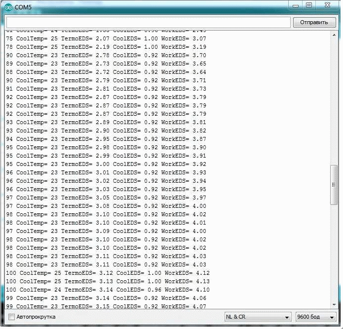
For debugging the thermometer, I output to the computer, besides the measured temperature: the temperature of the cold junction, thermo-EMF, EMF of the cold junction and the EMF of the hot junction.
// calculate the cold junction temperature
coolTemperature = (int)(((float)averageTemp * ADC_RESOLUTION / 500. - OFFSET ) / SCALE_FACTOR);
// thermo EMF calculation
termoEDS = (float)averageTermoEDS * ADC_RESOLUTION / 500. / (R4 / R3 + 1) - EDS_OFFSET;
// calculation of EMF of the cold junction
coolEDS = pgm_read_float(termTable + coolTemperature + 60);
// calculating the EMF of the hot junction
workEDS = termoEDS + coolEDS;
// calculating the temperature of the hot junction
temperature = 0;
if ( workEDS >= pgm_read_float(termTable + temperature + 380)) temperature += 380;
if ( workEDS >= pgm_read_float(termTable + temperature + 190)) temperature += 190;
if ( workEDS >= pgm_read_float(termTable + temperature + 95)) temperature += 95;
if ( workEDS >= pgm_read_float(termTable + temperature + 48)) temperature += 48;
if ( workEDS >= pgm_read_float(termTable + temperature + 24)) temperature += 24;
if ( workEDS >= pgm_read_float(termTable + temperature + 12)) temperature += 12;
if ( workEDS >= pgm_read_float(termTable + temperature + 6)) temperature += 6;
if ( workEDS >= pgm_read_float(termTable + temperature + 3)) temperature += 3;
if ( workEDS >= pgm_read_float(termTable + temperature + 2)) temperature += 2;
if ( temperature < 760 ) {
if ( workEDS >= pgm_read_float(termTable + temperature + 1)) temperature += 1;
}
temperature -= 60;
// display the temperature value on the LED
if (temperature >= 0) {
// the temperature is positive
disp.print((int)(temperature), 4, 1);
}
else {
// the temperature is negative
disp.digit[3]= 0x40; // отображается минус
disp.print((int)(temperature * -1), 3, 1);
}
// transfer the temperature of the hot junction to the computer
Serial.println(temperature);
/*
// transfer the cold junction temperature to the computer
Serial.print(" CoolTemp= "); Serial.print(coolTemperature);
// transfer the thermo EMF to the computer
Serial.print(" TermoEDS= "); Serial.print(termoEDS);
// transfer EMF of the cold junction to a computer
Serial.print(" CoolEDS= "); Serial.print(coolEDS);
// transfer EMF of the hot junction to the computer
Serial.print(" WorkEDS= "); Serial.println(workEDS);
*/
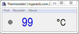
To use the thermometer with the Thermometer.exe top-level program from previous lessons, the transfer of this data to the computer must be disabled, leaving only the measured temperature.
You can download the resident program of Arduino thermometer for thermocouple at the link: sketch_27_1.zip.
Setting and calibration of the thermometer.
For practical use, the measuring amplifier of the thermometer should have sufficiently high metrological characteristics. I decided to avoid the use of any kind of adjustments with tuning resistors, and I performed all calibrations programmatically. Of course, it is desirable to use accurate, thermostable elements as resistors R3, R4, R5, R6. But even with 5% resistors, you can get good results when using a thermometer in conditions without significant fluctuations in ambient temperature.
I performed the following sequence of actions:
- I measured the voltage of the reference voltage source of the ADC board (1.1 V) with a voltmeter and calculated the resolution of the ADC:
#define ADC_RESOLUTION 1.061523 // resolution of the ADC, mV (1087 mV / 1024)
- Pre-measured the resistance of resistors R3, R4 and set their values in the program:
#define R3 1.61 // resistance of the resistor R3, kOhm
#define R4 44.2 // resistance of the resistor R4, kOhm
- I measured the EMF offset on the resistor R5 and set it in the program:
#define EDS_OFFSET 4.60 // offset thermo-EMF
- Then I placed the hot junction next to the cold junction (you can close the thermocouple leads) and corrected EDS_OFFSET so that the thermo-EMF was 0. The thermo-EMF value was controlled in the Arduino IDE serial port monitor.
Thus, we corrected all errors, except for temperature and time.
Using the Arduino thermometer in conjunction with a personal computer.
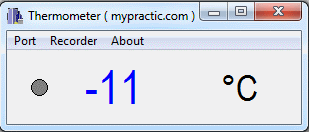
When the thermometer is connected to a computer, the functionality of the device expands. In particular, a function for recording temperature changes appears.
Don't forget to disable the debug data output block in the sketch.
/*
// transfer the cold junction temperature to the computer
Serial.print(" CoolTemp= "); Serial.print(coolTemperature);
// transfer the thermo EMF to the computer
Serial.print(" TermoEDS= "); Serial.print(termoEDS);
// transfer EMF of the cold junction to a computer
Serial.print(" CoolEDS= "); Serial.print(coolEDS);
// transfer EMF of the hot junction to the computer
Serial.print(" WorkEDS= "); Serial.println(workEDS);
*/
The Thermometer program from lesson 24 should be installed on the computer. In this lesson there is a detailed description of the program, you can also download the program there.
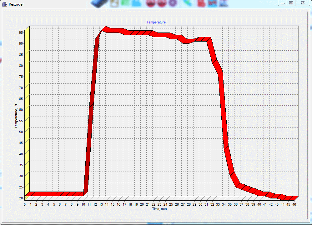
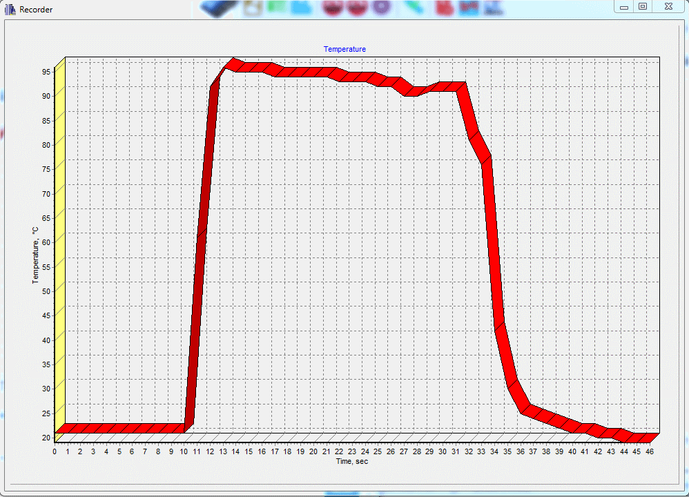
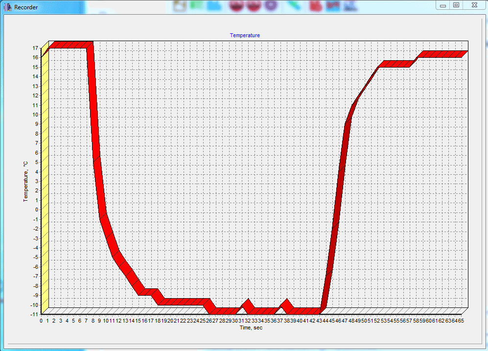
In this diagram, the temperature change of the thermocouple, which I poured boiling water in a glass.
A sharp drop in temperature at the end of the diagram - I pulled the thermocouple out of the water. You can see how low inertia a thermocouple has.
Then I put the thermocouple into the ice.
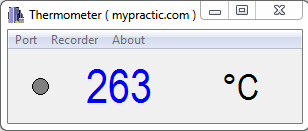
I measured the temperature of the soldering iron tip.
I don't know how accurate the thermometer is. At least we used the most accurate method of measuring temperature with a thermocouple.



thanks a lot for explanation.
Very informative and simple language easily graspable
Thank you
Thanks for the nice words.
Very Nice explanation. Thank you for sharing!