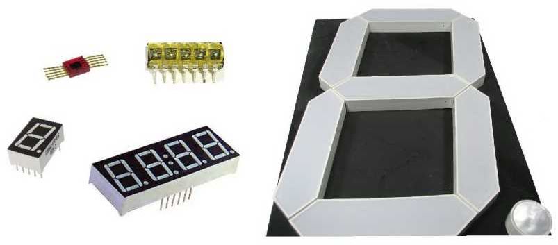
The lesson discusses the method of connecting a LED seven-segment display and a matrix of buttons to the Arduino board. A library for working with such a structure is presented.
Previous lesson List of lessons Next lesson
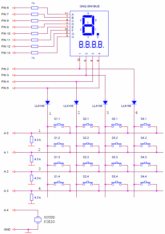
In previous lessons, we connected a matrix of buttons and a seven-segment LED display to the Arduino boards. It is easy to see that the signals for scanning the vertical lines of the matrix of buttons and the signals for selecting the digits of the display are absolutely similar in form, duration, amplitude. And their assignment is the same - to choose a group of buttons or LEDs. Why not use common signals for both the matrix of buttons and the display.
Here is the connection diagram for a matrix of buttons and the 4-digit LED display of the GNQ-3641BUE to Arduino board.
Having formed a high level on one of the display digit selection signals, we simultaneously select the vertical line of the matrix of buttons.
Such a connection scheme allows saving four pins of the board. Often, applications require one display and only 2-4 buttons. So, four buttons can be connected using only one extra pin.
On my breadboard, it all looks like this.
To control such a scheme in the Arduino system, I developed the LedDigitsKeys.h library. This library practically combines two libraries:
- Led4Digits.h, described in Lesson 20;
- MatrixKeys.h, described in Lesson 18.
The LedDigitsKeys.h library has the same methods and properties as its prototypes. The difference is that the regen() method simultaneously regenerates the display and scans the buttons. Of course, the constructor changed somewhat.
The LedDigitsKeys.h library for controlling a LED display and a matrix of buttons connected to the Arduino board using common pins.
You can download the LedDigitsKeys.h library from this link.
The library controls seven-segment LED displays:
- with dimension up to 4 digits;
- supports any variants of control pulse polarity;
- works as a parallel process;
- allows you to output on a seven-segment display:
- separate segments for each digit;
- characters for each digit;
- an integer from 0 to 9999;
- when outputting an integer, the number of digits is specified;
- blanking mode may be enabled.
For a button matrix the library:
- generates status signs for each button;
- forms the signs "was pressed" (clicks) for each button;
- eliminates contact bounce.
Constructor.
LedDigitsKeys (byte typeLed, byte digitPin0, byte digitPin1, byte digitPin2, byte digitPin3,
byte segPinA, byte segPinB, byte segPinC, byte segPinD,
byte segPinE, byte segPinF, byte segPinG, byte segPinH,
byte horizontalPin1, byte horizontalPin2, byte horizontalPin3, byte horizontalPin4,
byte numAckn);
typeLed Specifies the polarity of the control pulses for the selection signals of the digits and segments. Supports any wiring diagrams (Lesson 19).
| typeLed | Digits | Segments | Type of circuit |
| 0 | -_- | -_- | Common anode with digit selection switches |
| 1 | _-_ | -_- | Common anode |
| 2 | -_- | _-_ | Common cathode |
| 3 | _-_ | _-_ | Common cathode with digit selection switches |
digitPin0 ... digitPin3 - the digits selection pins. If digitPin = 255, then the digit is disabled. This allows you to connect indicators with fewer digits. digitPin0 - low (right) digit.
segPinA ... segPinH - the segments control pins.
horizontalPin1 ... horizontalPin4 - pins for the horizontal lines of the matrix.
numAckn - the number of acknowledgments of the buttons.
// display type 1; pins for digits 5,4,3,2; segment pins 6,7,8,9,10,11,12,13;
// horizontal lines of the button matrix: 14,15,16,17; number of acknowledgments 6
LedDigitsKeys disp (1, 5,4,3,2, 6,7,8,9,10,11,12,13, 14,15,16,17, 6);
The void regen() method.
The method must should be called in a parallel process with a refresh rate. It scans the matrix of buttons and regenerates the display.
// interrupt handler 2 ms
void timerInterrupt () {
disp.regen (); // regeneration of the display
}
The byte digit[4] array.
Controls the state of the display segments. A bit state of 1 causes the corresponding segment to glow. digit [0] is the low-order digit, the low-order bit is the ”A” segment.
digit [0] = B0000110; // to light B and C segments of the low digit
Method void tetradToSegCod (byte dig, byte tetrad)
Allows you to display numbers and letters of the hexadecimal code on the individual digits of the display. Arguments:
- dig - digit number 0 ... 3;
- tetrad - decimal code of the symbol.
tetrad (0, 3); // the number 3 in the low digit
The boolean print(unsigned int value, byte digitNum, byte blank) method.
The method outputs an integer on the display.
- value - the number that is displayed.
- digitNum - the quantity of digits for the displayed number. Allows you to use only part of the digits of the display. To the rest, you can output characters using other methods.
- blank - sign of blanking of non-significant zeros. blank = 0 means the number is displayed with all zeros. When blank is different from 0, insignificant digits are extinguished.
disp.print (i, 4, 1); // output variable i, 4 digits, blanking
disp.print (i, 3, 0); // output variable i, 3 digits
When the size of the number exceeds the allowable range, taking into account the number of digits, the function will display ”---” and return an error sign - false.
Arrays flagPress [4] [4] and flagClick [4] [4].
- flagPress - signs of the buttons status. True means the button is currently pressed.
- flagClick - signs that the buttons has been pressed (clicks). They are generated by pressing the button and must be reset programmatically.
Details on all these methods can be found in lesson 18 and lesson 20. There are also examples and programs for testing functions.
An example of using the library.
As an example of using the LedDigitsKeys.h library, we will write a program that outputs the characters of the pressed buttons on the LED display.
// LED display and matrix of buttons
#include <LedDigitsKeys.h>
#include <MsTimer2.h>
#define SOUND_PIN 18 // sound emitter pin
// the display type 1; digit pins 5,4,3,2; segment pins 6,7,8,9,10,11,12,13;
// horizontal lines of the button matrix: 14,15,16,17; number of confirmations 6
LedDigitsKeys disp(1, 5,4,3,2, 6,7,8,9,10,11,12,13, 14,15,16,17, 6);
// array of button codes
const byte codKeys[4][4] =
{ {1, 4, 7, 0xb},
{2, 5, 8, 0 },
{3, 6, 9, 0xd},
{0xe, 0xe, 0xe, 0xe}
};
byte soundCount=0; // sound time counter
void setup() {
MsTimer2::set(2, timerInterrupt); // timer interrupt 2 ms
MsTimer2::start(); // enable interrupt
pinMode(SOUND_PIN, OUTPUT); // sound pin
}
void loop() {
// calculation of the pressed button code
// columns
for (int i = 0; i < 4; i++) {
// lines
for (int j = 0; j < 4; j++) {
if (disp.flagClick[i][j] == true) {
disp.flagClick[i][j]=0;
// button pressed, digit shift
disp.digit[3]=disp.digit[2];
disp.digit[2]=disp.digit[1];
disp.digit[1]=disp.digit[0];
disp.tetradToSegCod(0, codKeys[i][j]);
soundCount= 30; // sound for 30 * 2 ms
}
}
}
}
//------------------------ interrupt handler 2 ms
void timerInterrupt() {
disp.regen(); // regeneration of the display
// sound
if (soundCount != 0) {
digitalWrite(SOUND_PIN, ! digitalRead(SOUND_PIN));
soundCount--;
}
}
The program determines the code of the pressed button and displays it.
The sound at the touch of a button is formed in the interrupt handling function. The pin state for the sound is inverted until the soundCount counter becomes 0. Thus, in order to initiate a sound signal, the signal duration in interrupt periods must be loaded into this counter. Formation of simple sound signals in this way is the most preferred option. No system timers are used.
In the next lesson we will learn to work with time, we will create a sports stopwatch on the Arduino.


