Let's learn how to connect a matrix of buttons to the Arduino board and use the standard tone() function to generate sound.
Previous lesson List of lessons Next lesson
In previous lessons, we connected buttons to the controller, using a separate input for each of them. If it is necessary to use a large number of buttons in the system, this solution may not be acceptable. Just not enough pins of the microcontroller.
There is another way to connect buttons to the Arduino board — by combining buttons into a matrix.
Connecting a matrix of buttons to the microcontroller.
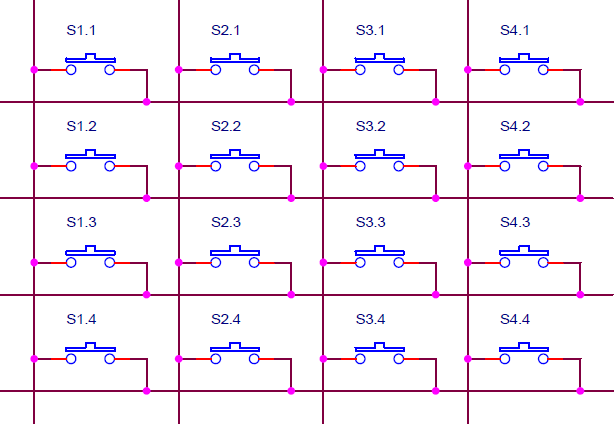
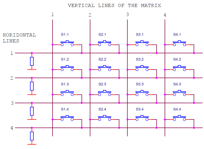
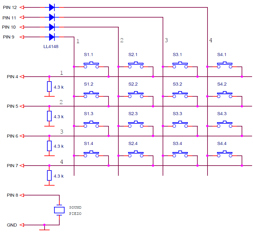
Here is an example of the scheme of such a matrix. Connecting 16 buttons requires only 8 pins of the microcontroller.
The buttons are connected to the vertical and horizontal lines of the matrix. The state of the buttons for each vertical line is checked separately. A high level signal (5 V) is applied to the vertical line and the states of the horizontal lines are read. A high level in the horizontal line will indicate that the corresponding button is pressed. Further, the remaining vertical lines are checked.
The resistors provide zero voltage at the inputs of the microcontroller with the buttons open.
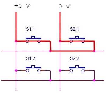
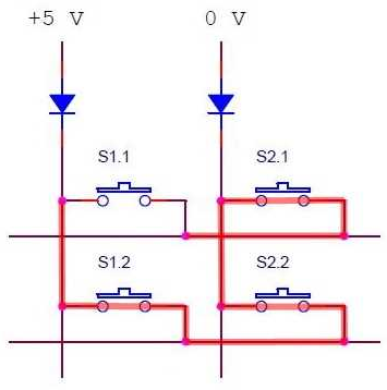
This scheme is often used to connect a matrix of buttons to the Arduino board in practical applications. That surprises me. After all, this scheme does not work correctly when simultaneously pressing two or more buttons from the same horizontal line. In this case:
- The result will be unpredictable. Through the horizontal line and the two pressed buttons closed vertical lines with high and low levels of the signal. What vertical line will draw, this level will be on the horizontal line.
- There will be a closure of microcontroller pins with different signal levels. At best, the current consumption will increase, and the microcontroller will heat up.
To eliminate this problem, it is enough to connect vertical lines through the diodes. Then the closure of the controller pins is impossible with any number of simultaneously pressed buttons. Also, a circuit with diodes will allow you to correctly determine the state of the matrix with two buttons simultaneously pressed. When the three adjacent buttons are pressed, the fourth closes.
Connecting a matrix of buttons to the Arduino board.
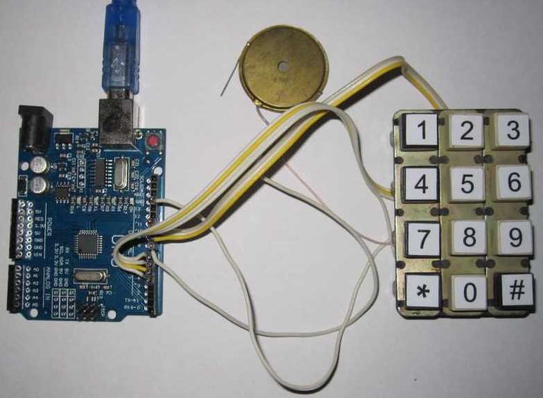
Let's connect the matrix of 3x4 buttons to the Arduino board using this scheme.
A good style is to press each button with a short beep. To do this, we connect a sound piezo emitter to the board. I have it all look like this.
4 x 4 keyboard matrix scanning library.
I developed a library for scanning keyboard matrix MatrixKey.h.
You can download it at the link MatrixKey.h.
How to install is written in lesson 9.
The MatrixKey library:
- determines the current state of each button;
- generates signs "was pressed" for each button (clicks);
- eliminates bounce contacts of buttons;
- the matrix is scanned in a parallel process, the main program works only with ready-made signs.
The library has a constructor and only one function.
MatrixKeys (byte verticalPin1, byte verticalPin2, byte verticalPin3, byte verticalPin4, byte horizontalPin1, byte horizontalPin2, byte horizontalPin3, byte horizontalPin4, byte numAckn)
The constructor creates an object with the specified parameters.
- verticalPin1, verticalPin2, verticalPin3, verticalPin4 - pin numbers for connecting vertical lines of the matrix 1, 2, 3, 4;
- horizontalPin1, horizontalPin2, horizontalPin3, horizontalPin4 - pin numbers for connecting horizontal matrix lines 1, 2, 3, 4;
- numAckn - the number of confirmations of the status of contacts.
// create an object matrix of keys
// connect vertical lines to pins 9, 10, 11, 12
// connect horizontal lines to pins 4, 5, 6, 7
// number of confirmations of the status of contacts = 6
MatrixKeys keys (9, 10, 11, 12, 4, 5, 6, 7, 6);
Separate matrix pins can be disabled by setting the numbers for them in the constructor to 255. This may be required when connecting a matrix of a lower dimension.
void scanState ()
The method scans the state of the matrix buttons. It has no parameters, returns nothing.
To eliminate the bounce of buttons, the way to wait for the stable state of contacts is used, as described in Lesson 6. In a parallel process, the scanState () method should be called regularly.
// -------------------------------------- interrupt handler 2 ms
void timerInterrupt () {
keys.scanState (); // scan matrix
}
As a result, the signs of flagPress [4] [4] and flagClick [4] [4] arrays are formed:
- when the button is pressed flagPress = true;
- when the button is free flagPress = false;
- at the moment of pressing the button flagClick = true button.
The flagPress sign shows the current state of the button and changes its value depending on the state of the button.
The flagClick flag becomes active at the moment the button is pressed and remains in this state until it is cleared by the program. The MatrixKeys class only sets it to the active state.
A typical operation with the flagClick flag is to check the sign in the main loop, reset it and perform a specific action scheduled at the touch of the button. This flag remembers the event - the button was pressed and stores information about it until it is reset.
Unlike the known Keypad library, the MatrixKeys library:
- much smaller and faster;
- focused on use in a parallel process, the main program works only with ready-made signs;
- reliably handles contact bounce, allows you to set the number of confirmations of the status of buttons;
- the matrix is scanned regularly, with a certain period without gaps and delays.
Standard sound generation function tone().
To generate a sound signal by pressing the buttons, you can use the standard tone() function. The function generates a rectangular signal at the specified output.
void tone (pin, frequency)
void tone (pin, frequency, duration)
Arguments:
- pin - pin number;
- frequency - frequency of the signal in Hz;
- duration - the duration of the signal in milliseconds.
If the signal duration is not specified by the third argument, the signal is generated until the noTone() function is called.
It must be remembered that to generate a signal, the tone () function uses the Timer 2 of the Arduino board. Therefore, if this timer is already used in the program, for example, to form an interrupt, the tone () function can lead to a conflict in accessing timer 2. For this reason, I have not created in the class the possibility of tracking the button presses with a sound signal.It is better to do this outside the class, using your own method in each specific case.
Practical use of the MatrixKeys library.
Let's develop a simple program for checking and demonstrating the MatrixKeys.h library. The program transmits to the computer via the serial port the status of the keyboard matrix :
- the pressed button is displayed as “*”;
- the free button - ".";
- the moment the button is pressed (click) is displayed with “=” symbol for 0.5 seconds.
// keyboard matrix
#include <MatrixKeys.h>
#include <MsTimer2.h>
// create an object matrix of keys
// connect vertical lines to pins 9, 10, 11, 12
// connect horizontal lines to pins 4, 5, 6, 7
// number of confirmations of the status of contacts = 6
MatrixKeys keys(9, 10, 11, 12, 4, 5, 6, 7, 6);
void setup() {
Serial.begin(9600); // initialize the port, rate 9600
MsTimer2::set(2, timerInterrupt); // set the timer interrupt period 2 ms
MsTimer2::start(); // enable timer interrupt
}
void loop() {
// lines
for (int i = 0; i < 4; i++) {
// columns
for (int j = 0; j < 4; j++) {
if (keys.flagClick[j][i] == true) { Serial.print("="); keys.flagClick[j][i]=false; tone(8,1000,50); }
else { if (keys.flagPress[j][i] == true) Serial.print("*"); else Serial.print("."); }
}
Serial.println(" ");
}
Serial.println(" ");
delay(500);
}
//-------------------------------------- interrupt handler 2 ms
void timerInterrupt() {
keys.scanState(); // scan matrix
}
Download the program to the board. Don't forget to install the MatrixKeys.h and MsTimer2.h libraries. Open the serial monitor. On the screen, every 0.5 seconds, the matrix state blocks will run through.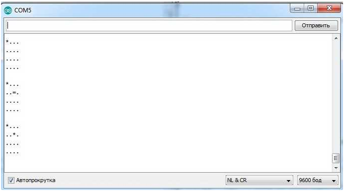
By clicking on the buttons of the matrix, you can check the operation of the program.
If it is necessary to transmit the code of the pressed key, then it is possible to convert the array of click signs keys.flagClick [4] [4] into the codes of buttons codKeys [4] [4].
// keyboard matrix
#include <MatrixKeys.h>
#include <MsTimer2.h>
// array of button codes
const char codKeys[4][4] =
{ {'1', '4', '7', '*'},
{'2', '5', '8', '0' },
{'3', '6', '9', '#'},
{' ', ' ', ' ', ' '}
};
// create an object matrix of keys
// connect vertical lines to pins 9, 10, 11, 12
// connect horizontal lines to pins 4, 5, 6, 7
// number of confirmations of the status of contacts = 6
MatrixKeys keys(9, 10, 11, 12, 4, 5, 6, 7, 6);
void setup() {
Serial.begin(9600); // initialize the port, rate 9600
MsTimer2::set(2, timerInterrupt); // set the timer interrupt period 2 ms
MsTimer2::start(); // enable timer interrupt
}
void loop() {
// calculation of the code of the pressed button
// columns
for (int i = 0; i < 4; i++) {
// lines
for (int j = 0; j < 4; j++) {
if (keys.flagClick[i][j] == true) {
keys.flagClick[i][j]=0;
Serial.println(codKeys[i][j]);
}
}
}
}
//-------------------------------------- interrupt handler 2 ms
void timerInterrupt() {
keys.scanState(); // scan matrix
}
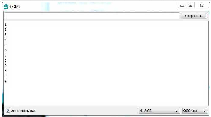
If you load the program into the board and open the serial port monitor, then each time you press a button, the symbol corresponding to the button will be displayed in the monitor window.
If necessary, you can easily convert the library to a keyboard matrix of other dimensions.
In the next lesson we will connect seven-segment LED indicators to the Arduino board.

Hi
I am trying to create a similar function that will scan a matrix 4 column by 30 rows, these do have rectifiers on and i cannot remove as the project it to test the function.
i did manage to make work on a uno up to 6 row and need more rows.
Ps
Have tried on a mega and no joy.
noticed the mstimer2.cpp says support for atmega 1280,328,128 but not 2560
does this mean will not work on mega ?
Hi!
There is a similar library for Mega2560, FlexiTimer2.
excellent the 4×4 works fine, can this system run a larger matrix say 4 x 20?