The article presents a simple security alarm project, a description of the operation, resident software (firmware). The device is not difficult to assemble with your own hands. All the information necessary for this is in the article.
General description of the device.
The burglar alarm system is developed by using PIC controller PIC12F629. This is a microcontroller with 8 pins and a price of only 0.5 $. Despite the simplicity and low cost, the device provides control of two standard security alarm loops. The system can be used to protect fairly large objects. The device is controlled by a remote control with two buttons and one LED.
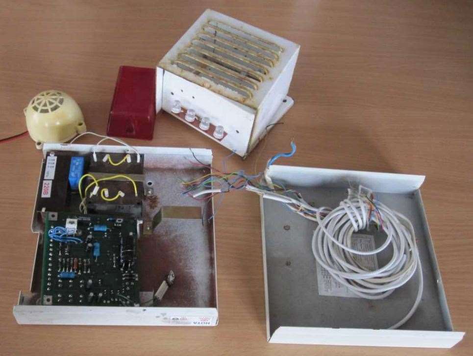
Our company moved to a new building. From the previous owners left the old burglar alarm. It was an iron box with red LEDs and a siren above the front door and a disassembled electronic unit.
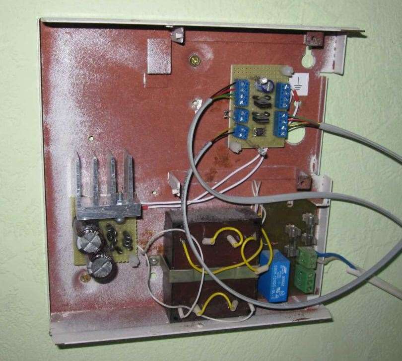
I installed a small board in the alarm unit and turned this stuff into a modern, reliable security alarm system. At the moment, it is used to guard a two-story building with a total area of 250 m2.
So, the alarm provides:
- Monitoring of two standard security loops with measurement of their resistance and digital filtering of signals.
- Remote control (two buttons and one LED):
- alarm activation;
- disabling alarm through a secret code
- setting a secret code (the code is stored in the internal non-volatile memory of the controller);
- indication of the operating mode by the remote control LED.
- The device generates the time delays necessary to dial the secret code, close the doors of the room, etc.
- When an alarm is triggered, the device turns on the sounder (a siren).
- The mode of operation of the device is also displayed by an external light source.
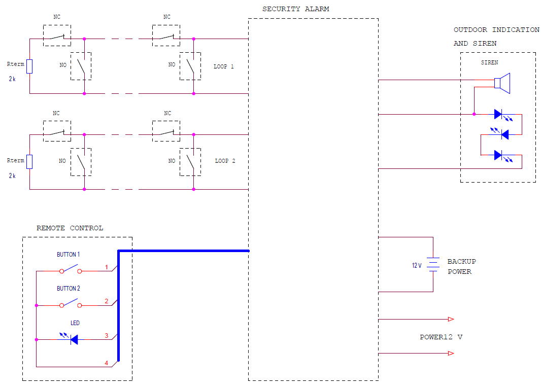
The security alarm block diagram looks like this.
To the main block of the alarm system are connected:
- 2 security loops with:
- NC - normally closed sensors;
- NO - normally open sensors;
- Rterm - terminal resistors.
- Remote Control.
- External block of the sound notification and indication of the mode.
- Backup power source.
- Power supply unit 12 V.
Security alarm loops and sensor wiring.
To control sensors (detectors), the device uses standard security loops. Loop resistance is monitored. If the resistance of the circuit is greater than the upper threshold or less than the lower, an alarm is generated. Normal is the resistance of the loop equal to the terminal resistor (2 kΩ). Thus, if the attacker breaks the wires of the cables or closes them, the alarm will work. This way to disable security sensors will not work.
The following loop resistance thresholds are selected in this device.
| Loop resistance | |
| Nominal value | 2000 Ohm |
| Upper threshold | 5900 Ohm |
| Lower threshold | 540 Ohm |
Those, loop resistance in the range of 540 ... 5900 ohms is considered normal. If the resistance value is out of this range, then an alarm is triggered.
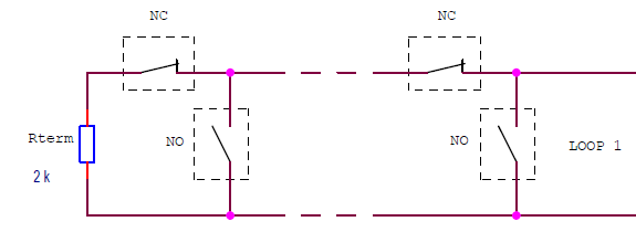
Connection diagram of sensors (detectors) to the security loop.
Both normally closed security sensors (NC) and normally open (NO) can be connected to one loop. The main thing is that in normal condition the circuit should have a resistance of 2 kΩ, and when any sensor is triggered, it would cause an open or a short circuit.
To increase the noise immunity of the system, digital filtering of the loop signals occurs in the device.
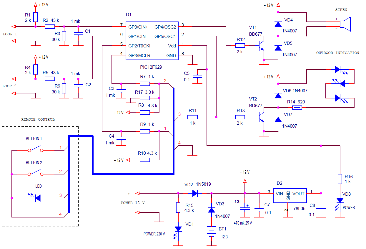
Schematic diagram of the alarm system.
In principle, everything should be clear. Connected to the PIC12F629 microcontroller:
- Two loops through RC chains R1-R6, C1, C2, providing
- formation of loop feed current;
- analog signal filtering;
- matching with the input levels of the PIC controller inputs.
A microcontroller comparator is used to determine the loop resistance. An internal voltage source is connected to the second input of the comparator. The values of the reference voltage source for comparison with the upper and lower threshold resistance values are set programmatically.
| Loop resistance | Voltage at inputs GP0, GP1 (threshold voltages) |
| 5900 Ohm | 3,6 V |
| 2000 Ohm | 2,43 V |
| 540 Ohm | 1,04 V |
- Two buttons of the remote are connected via RC chains R7-R10, C3, C4. The LED is connected through the current-limiting resistor R11. The device provides digital filtering of the button signals to eliminate bounce and increase noise immunity.
It is necessary to clarify the purpose of the resistor R17. The GP3 input of the microcontroller has an alternative function - powering 12 V for programming the chip. Therefore, it does not have a protective diode that limits the voltage at the supply voltage level. At 12 volts on this pin, the microcontroller goes into programming mode. Resistor R17 reduces the voltage at the GP3 input.
- Through two transistor switches VT1, VT2, the microcontroller controls the siren and external LED indication. Since these elements can be connected with a long cable, the transistors are protected from line emissions by diodes VD4-VD7. Transistor switches allow switching current up to 2 A.
- A voltage of 5 V to power the PIC controller is produced by the D2 stabilizer. Do not ignore the VD8 LED. Its functions include not only the indication of power, but also the creation of a minimum load for the microcontroller. If the PIC controller consumes less than 2-3 mA of current (for example, in reset mode), the voltage of 12 V through the resistors R8, R10 can raise the supply voltage of the microcontroller above the permissible.
- The inputs for the 12 V power supply and backup power source are disconnected by VD2, VD3 diodes. A Schottky diode is used as a VD2 diode in order to give priority to the power supply unit with equal voltage with a backup power source.
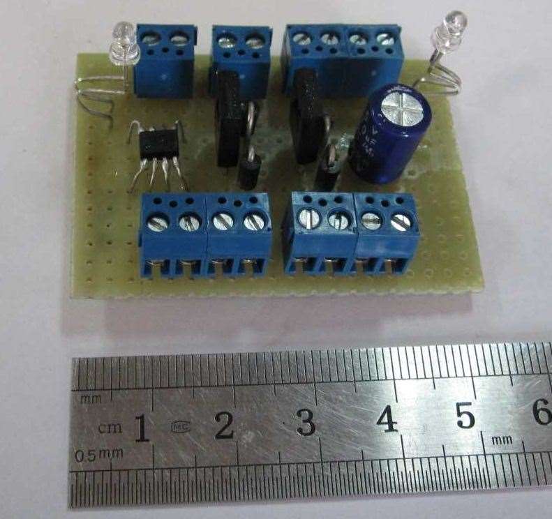
I assembled the device on a 54 x 45 mm board.
I installed it in the old system case. Left only the power supply.
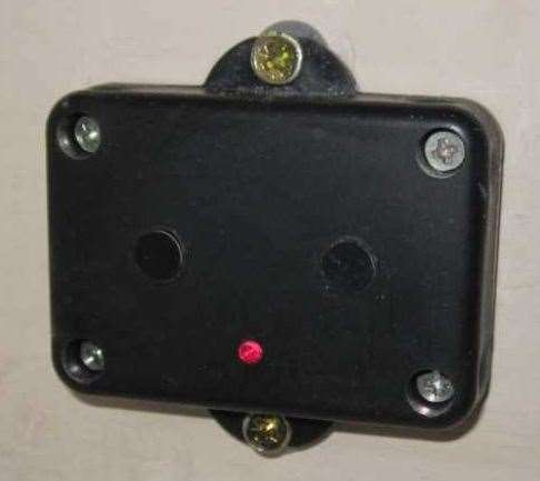
The console is made in a plastic case with dimensions of 65 x 40 mm
The software.
The resident software is developed in assembler. In the program, all variables and registers are reistalled cyclically. The program can not hang.
You can download firmware for PIC12F629 in HEX format here.
Control of the alarm system from the panel.
The remote is a small box with two buttons and a LED.
It is better to install it indoors near the front door. With the help of the remote, the alarm is turned on and off, the secret code set.
Modes and controls.
The first time the power is supplied, the device enters disabled mode. The LED does not glow. In this mode, the device is during the working day.
To activate the alarm (security mode), you must click on two buttons at once. The LED will blink rapidly, and after 20 seconds the device will enter security mode, i.e. will begin to monitor the status of the sensors. This is the time it takes to get out of the room and close the front door.
If during this period of time (20 seconds) to press any button, the device will cancel the security mode and return to disabled mode. Often people remember something just before leaving the building.
20 seconds after switching on, the device will switch to security mode. In this mode, the LEDs of the console and the external display unit flash approximately once per second. In security mode, the state of the sensors is monitored.
When any security sensor is triggered, the LEDs blink rapidly and the device counts down the time after which the siren will sound. This time (30 seconds) is necessary in order to have time to turn off the security alarm by typing the secret code on the remote control buttons.
On the remote there are 2 buttons. Therefore, the code looks like a number from digits 1 and 2. For example, the code 121112 means that you need to press the buttons 1, 2, three times 1 and 2 in succession. The code can have from 1 to 8 digits.
If the code is typed incorrectly or incompletely, you can press two buttons at the same time and repeat the code set.
With a correctly dialed code, the device enters disabled mode.
If within 30 seconds after the sensor has triggered, the correct code has not been dialed, the siren will turn on. You can disable it by typing the correct code. Otherwise, the siren will sound for 33 seconds, and then the device will turn off (will go into disabled mode).
It remains to explain how to set the secret code. This can only be done from disabled mode.
It is necessary to keep both buttons pressed for 6 seconds. Release when the remote LED lights up. This will mean that the device has switched to the secret code setting mode.
Then you just need to dial a new secret code. Not more than 8 digits. The pause between pressing the buttons should not exceed 5 seconds.
Then wait until the LED goes out (5 seconds). The device will enter disabled mode and the new code will be stored in the internal non-volatile memory of the microcontroller.
Since the microcontroller of the device is clocked from the internal generator of low accuracy, then the indicated time parameters can differ by ± 10%.
The security alarm status.
| Mode | LED state | Transition condition | Transition to mode |
| ALARM DISABLED | Not lit. | Short press two buttons at the same time. | Waiting for security mode (20 sec).
It is necessary to go out and close the front door. |
| Hold two buttons for 6 sec. | Setting a secret code. | ||
| Waiting for security mode.
It is necessary to go out and close the front door. |
Frequently flashes. | Time 20 sec. | SECURITY |
| Press any button (cancel). | ALARM DISABLED | ||
| SECURITY | Flashing once a second. | Sensor triggers. | Time to turn off the alarm by code (30 sec).
Necessary in order to turn off the alarm by dialing the code. |
| Time to turn off the alarm by code (30 sec).
Necessary in order to turn off the alarm by dialing the code. |
Fast flashing. | The correct code has been dialed. | ALARM DISABLED |
| The correct code is not dialed within 30 seconds. | ALARM (Siren sound) |
||
| ALARM (Siren sound) |
Fast flashing. | The correct code has been dialed. | ALARM DISABLED |
| Time 33 sec. | ALARM DISABLED | ||
| Setting a secret code. | Lit. | Code set. | ALARM DISABLED |
Practically work with the security alarm is reduced to action.
- Leaving the premises. Press two buttons at the same time and close the door for 20 seconds.
- Entering the premises. Within 30 seconds dial the secret code.
Disadvantages, possible improvements.
The device can be easily modified for its specific conditions. All improvements concern only the hardware. They do not affect the software.
- It is advisable to install two sirens. One in the outdoor display and warning unit, the other in a hard-to-reach place. The transistor switch current (2 A) allows this.
- It would be necessary to protect the siren wires from short-circuiting by a transistor current regulator. In the presented variant of the scheme, an attacker can close the siren wires and when the alarm is triggered, the power supply will short circuit.
- If desired, powerful and high-voltage sources of light, sound, etc. can be connected via electromagnetic relays. . The permissible current of the transistor switches allows to do this, and they are protected against emissions when switching the relay winding.
- As a backup power supply, you can use a battery by adding a simple charge circuit.
The appearance of the installed alarm system.
If only one loop is used, then a resistor of 2 kΩ must be connected to the second.
Improvements of the software.
The device was developed 2 years ago. It was implemented many times. There were a few comments on the software. Therefore, I developed several versions of the program.
Rosalyn from Bulgaria wrote that it is necessary to eliminate the delay in triggering the alarm on the second loop.
The delay is needed only for the loop to which the control sensors of the entrance door are connected. The delay is necessary in order to quietly enter and disable the alarm.
For window control sensors or fire detectors, the alarm should be triggered instantly. Why give the opportunity to the attacker, who climbed through the window, to enjoy the extra 30 seconds of silence. Also, it is unlikely that anyone thinks that before notifying of a fire it is necessary to give half a minute to burn.
I added this feature to the alarm. In the new version, the operation of any sensor on the second loop generates an alarm without delay.
Another variant.
Now when the sensors are triggered, a siren sounds for 30 seconds. Then the state of the loops is checked.
If the sensors are normal, the device enters security mode, i.e. again controls the state of loops.
If the alarm signal from the sensors remains, then the alarm is turned off.
Here is the program for this option.
Changed the time of arm and disarm for 10 seconds. Although, it seems to me, it is not enough.
I was asked in version 1.3 to increase the siren time to 2 minutes. Corrected.
In our company, the alarm system has successfully worked for 2 years. When we purchased another building, assembled the exact same device.
The site has a draft full analogue of the device based on the Arduino board..


