We learn about another way of processing the button's signal to filter out noise and eliminate contacts bounce.
Previous lesson List of lessons Next lesson
In lesson 6, we considered one of the ways to eliminate the bounce of button's contacts and wrote a program for its implementation.
Let's call this method the expectation of a stable state of contacts. Let me remind you of its algorithm. The decision about the state of the button contacts is accepted after the signal state has become stable (stopped changing) for the specified time. A very reliable method for eliminating the bounce of contacts.
But in addition to the bounce of contacts in the signal there are also electromagnetic interference. We said that together with the bounce, the method of waiting for a stable state of contacts eliminates interference. Let's see how this method will handle a signal with regular impulse noise.
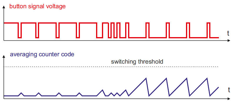
The first diagram is the signal of the button's contacts with bounce and impulse noise. The second diagram is the counter code that counts the time of a steady state of the signal. It can be seen that short interference pulses reset the counter. Hence, its value never reaches the switching threshold, and the sign of the button pressing will not be formed. Those. the stable state waiting algorithm will never allocate the switching of contacts in such a signal, although it is clearly visible that in the middle of the diagram the contacts closed.
But this situation is quite real.
- The button can be connected to the controller by long wires. An example is a button on the remote control located at a considerable distance from the controller. In this case, pulses of electromagnetic interference can be present in the signal.
- In addition to the buttons, there are many different components with mechanical contacts in electronic systems: relays, switches, sensors, limit switches, etc. All of them require elimination of the bounce and, as a rule, are connected to the controller by long wires.
- There are a large number of components that do not have mechanical contacts, but which are almost always installed at a considerable distance from the controller. For example, optical sensors used to monitor the position of mechanical equipment components.
- Signals, communications between electronic devices located at a great distance from each other, are also subject to electromagnetic interference and require software processing.
A typical example is security alarm.
A remote control with buttons is located a few meters away from the controller.
At a distance of several tens or even hundreds of meters, a number of security sensors of various types are connected to the controller. It can be contact sensors, reed sensors, intelligent sensors with relay or optoisolated output, fire sensors. Imagine what opportunities for the effects of interference! Without digital signal filtering, such systems will not work.
So:
- When we talk about buttons, we mean any components with mechanical contacts: relays, reed switches, limit switches, etc. These elements also have a bounce of contacts.
- Any external signal, even without switch bounce, is subject to electromagnetic interference and must be processed by the program to increase noise immunity.
In all these cases, digital signal filtering should be used, which significantly improves immunity to electromagnetic interference.
There are very complicated algorithms for digital signal processing. In our case, a simple averaging of the signal level is sufficient. According to the diagram shown above, we easily determine the signal state. We simply see that in the first half of the chart the average level is clearly high, and in the second half - low. And short interference does not prevent us from visually determining the signal state.
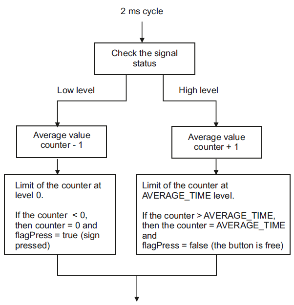
The averaging algorithm is quite simple and looks like this. We need a average value counter and a constant AVERAGE_TIME - the averaging time.
- In a cycle, with a certain period (for example, 2 ms), we read the signal state.
- If it is low, then subtract from counter 1. If high, add 1.
- The value of the counter is limited from below at the level 0 and from above at the level of the constant determining the averaging time.
- Thus, the counter contains the average value of the signal level.
- When the contents of the counter reaches 0, a decision is made that the contacts are closed.
- When the content of the counter reaches the limit value - constants AVERAGE_TIME, the decision is made that the contacts are open.
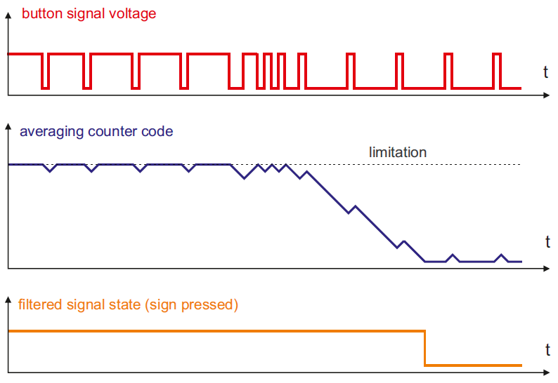
Here are diagrams showing the operation of the signal averaging algorithm.
Such an algorithm will easily determine the state of contacts even with regular interference. The main thing is that the average level of interference is less than the average signal level.
It must be remembered that digital filtering by this method introduces a temporary delay in determining the signal state. Those. It can be used only for sufficiently slow signals - with a response of tens of ms. All components with mechanical contacts do not switch faster.
Implementation of the algorithm for digital signal filtering in Arduino program.
I suggest not creating a separate class, but adding a method for the Button class created in the previous lesson. As I have already said, a button means any electronic element that requires the software to process its signal. So let's do digital filtering in the same class, realizing that this class can be used not only for a button.
Let's call the method filterAvarage (average filtering).
We believe that only one of the two signal processing methods can be used in the class:
- scanState () - scanning the status (was created in the previous lesson);
- filterAvarage () - filtering by the average value.
In this case, we do not need to create new variables. We can use the same signs, the same variables. Restriction - you can call only one of the methods for each object. From the point of view of object-oriented programming, this is not very good, but we remember that the resources of our controller are limited. Such universality will not create problems for us.
Let's add the filterAvarage() method in the Button class description.
class Button {
public:
void filterAvarage(); // method of filtering the signal by average value
. . . . . . . . . . . . . // other members of the class
};
Let's write the code for the new method.
// method of filtering the signal by average value
// for a low-level signal flagPress = true
// for a high-level signal flagPress = false
// when the state changes from high to low flagClick = true
void Button::filterAvarage() {
if ( flagPress != digitalRead(_pin) ) {
// button state remains the same
if ( _buttonCount != 0 ) _buttonCount--; // counter of acknowledgments - 1 with limitation to 0
}
else {
// button state changed
_buttonCount++; // +1 to acknowledge counter
if ( _buttonCount >= _timeButton ) {
// the signal state reached the threshold _timeButton
flagPress= ! flagPress; // inversion of the state sign
_buttonCount= 0; // reset acknowledge counter
if ( flagPress == true ) flagClick= true; // sign of the button click
}
}
}
Now, let's create 2 objects of the button type in the program from the previous lesson. The first one will be processed by the method of filtering by the average value, and the second by the method of waiting for a stable state. As before, we will invert the state of the LED on the Arduino board with the first button, and by pressing the second button - invert the state of the LED on the breadboard.
Here is the complete code of the program. (sketch_8_1)
// sketch_8_1 lesson 8
// 2 buttons and LED are connected to the board
// Each press of button 1 changes the LED status on the Arduino board
// Each press of button 2 changes the status of the LED on the breadboard
#define LED_1_PIN 13 // LED 1 is connected to pin 13
#define BUTTON_1_PIN 12 // button 1 is connected to pin 12
#define BUTTON_2_PIN 11 // button 2 is connected to pin 11
#define LED_2_PIN 10 // LED 2 is connected to pin 10
// Description of the button signal processing class
class Button {
public:
Button(byte pin, byte timeButton); // constructor
boolean flagPress; // button in the pressed state
boolean flagClick; // button was clicked
void scanState(); // method for scaning the signal state
void filterAvarage(); // method of filtering the signal by average value
void setPinTime(byte pin, byte timeButton); // method of setting the pin number and acknowledge time
private:
byte _buttonCount; // counter of button state acknowledgments
byte _timeButton; // time of button state acknowledgment
byte _pin; // pin number of button
};
boolean ledState1; // LED state variable1
boolean ledState2; // LED state variable2
Button button1(BUTTON_1_PIN, 15); // create an object for button1
Button button2(BUTTON_2_PIN, 15); // create an object for button2
void setup() {
pinMode(LED_1_PIN, OUTPUT); // define pin for LED1 as an output
pinMode(LED_2_PIN, OUTPUT); // define pin for LED2 as an output
}
// an infinite loop with a period of 2 ms
void loop() {
button1.filterAvarage(); // call method of filtering the signal by average value for button1
button2.scanState(); // call the method of scanning the signal state for button2
// LED control unit1
if ( button1.flagClick == true ) {
// button was clicked
button1.flagClick= false; // reset the button click flag
ledState1= ! ledState1; // change the state of the LED
digitalWrite(LED_1_PIN, ledState1); // display the status of the LED1
}
// LED control unit2
if ( button2.flagClick == true ) {
// button was clicked
button2.flagClick= false; // reset the button click flag
ledState2= ! ledState2; // change the state of the LED
digitalWrite(LED_2_PIN, ledState2); // display the status of the LED2
}
/*
// checking the flags button is pressed
digitalWrite(LED_1_PIN, button1.flagPress);
digitalWrite(LED_2_PIN, button2.flagPress);
*/
delay(2); // 2 ms delay
}
// method of filtering the signal by average value
// for a low-level signal flagPress = true
// for a high-level signal flagPress = false
// when the state changes from high to low flagClick = true
void Button::filterAvarage() {
if ( flagPress != digitalRead(_pin) ) {
// button state remains the same
if ( _buttonCount != 0 ) _buttonCount--; // counter of acknowledgments - 1 with limitatuon to 0
}
else {
// button state changed
_buttonCount++; // +1 to the acknowledge counter
if ( _buttonCount >= _timeButton ) {
// the signal state reached the threshold _timeButton
flagPress= ! flagPress; // inversion of the state sign
_buttonCount= 0; // reset acknowledge counter
if ( flagPress == true ) flagClick= true; // sign of the button click
}
}
}
// method for checking the status of the button
// when the flagPress = true button is pressed
// when the flagPress = false is free
// when you click flagClick = true
void Button::scanState() {
if ( flagPress != digitalRead(_pin) ) {
// button state remains the same
_buttonCount= 0; // reset acknowledge counter
}
else {
// button state changed
_buttonCount++; // +1 to the acknowledge counter
if ( _buttonCount >= _timeButton ) {
// the state of the button did not change for the time _timeButton
// the state of the button became stable
flagPress= ! flagPress; // inversion of the state sign
_buttonCount= 0; // reset acknowledge counter
if ( flagPress == true ) flagClick= true; // sign of the button click
}
}
}
// method of setting pin number and time of acknowledgment
void Button::setPinTime(byte pin, byte timeButton) {
_pin= pin;
_timeButton= timeButton;
pinMode(_pin, INPUT_PULLUP); // define the pin of the button as an input
}
// class constructor Button
Button::Button(byte pin, byte timeButton) {
_pin= pin;
_timeButton= timeButton;
pinMode(_pin, INPUT_PULLUP); // define the pin of the button as an input
}
Download the program to the controller. Check. You will see that the corresponding LEDs react to both buttons in exactly the same way. Simply, you are not able to simulate the signals of different duty cycles with a period of 30 ms.
The most scrupulous readers can test the work of the algorithm. To do this, we must artificially make the averaging time very large. The averaging time will be 5 seconds if you:
- when creating button objects, set the second parameter to the maximum value;
Button button1 (BUTTON_1_PIN, 250); // create an object for button 1
Button button2 (BUTTON_2_PIN, 250); // create an object for button 2 - Set the cycle time to 20 ms.
delay (20); // a delay of 20 ms
Now remove the LED control units from the button-click flags and make the LED control from the flags a button is pressed.
digitalWrite (LED_1_PIN, button1.flagPress);
digitalWrite (LED_2_PIN, button2.flagPress);
Now you can check that when you press the buttons, both LEDs light up with a delay of about 5 seconds. Again, the buttons work the same way.
But if you keep both buttons pressed for 3 seconds and free for one second in cycle, you will see that the second LED remains off. And the first LED with a long delay, but will light up.
We have finished creating the Button class. The button was not such a simple element. In the next lesson, we'll design this class as a library.


