The lesson describes the use of silicon temperature sensors in the Arduino system. The working project of the thermometer is given. Along the way, the issue of measuring resistance in the Arduino system is considered.
Previous lesson List of lessons Next lesson
In the previous lesson, we used integral sensors to measure temperature, in which the output voltage is proportional to the temperature. Moreover, this dependence is linear with a known scale factor. To calculate the temperature, it is enough to measure the voltage and divide it by a scale factor.
Silicon temperature sensors change their resistance depending on the temperature. These are not active elements that require power, not integrated circuits, but simply thermistors.
Typical representatives of silicon sensors are thermal sensors of the KTY81 series (KTY81.pdf).
Advantages and disadvantages of kty81 series temperature sensors.
Sensors of this type most developers simply do not notice. On the contrary, I believe that in some applications they are indispensable.
In my opinion, these devices have only one major drawback - a nonlinear characteristics and low measurement accuracy. The best variants of kty81 series sensors have nonlinearity:
- ± 3.5 °C in temperature range up to + 100 °C;
- ± 8.5 °C in the temperature range up to + 150 °C.
The non-linearity of the characteristic is corrected by the microcontroller program. In principle, it is possible to calibrate each sensor individually.
But if such measurement accuracy is acceptable, then for the rest of the characteristics and operational capabilities KTY81 significantly superior to the integrated temperature sensors. Namely:
- Silicon thermal sensors have a wide range of measured temperatures of -55 ... +150 ° C. As a rule, integrated devices operate in the range of -40 ... +125 ° C, many up to +100 ° C. Often these extra 25-50 ° C are not enough, for example, when controlling the temperature of radiators powerful semiconductor devices.
- Only two wires are required to connect to the microcontroller, which is especially important when the sensors are located at a great distance from the controller.
- High noise immunity is ensured due to a two-wire communication line that is symmetrical for interference. To connect the KTY81 sensor at a distance of tens or even hundreds of meters, a simple twisted pair is enough.
- High resistance KTY81 (1000 Ohm and 2000 Ohm) allows to neglect the active resistance of the communication wires.
- There is no limit to work with capacitive load. This quality makes it possible to use communication lines with a large capacity and to shunt the thermal sensor with a capacitor of significant capacity for filtering interference. Integrated temperature sensors do not work on capacitive load more than 10 nF.
- Devices do not have polarity. Many semiconductor devices have been incapacitated due to polarity error when connected.
- Low price. This is one of the cheapest temperature sensors.
Decide for yourself in which projects to use these sensors. In my designs – powerful cathodic protection stations on each radiator mounted temperature sensor KTY81/120.
Silicon Thermal Sensors KTY81 Series.
Details about these devices can be found at the link. Now I will briefly say that:
- the series includes 10 types of sensors with different measurement accuracy and resistance;
- all devices have an operating temperature range of 55 ... + 150 °C;
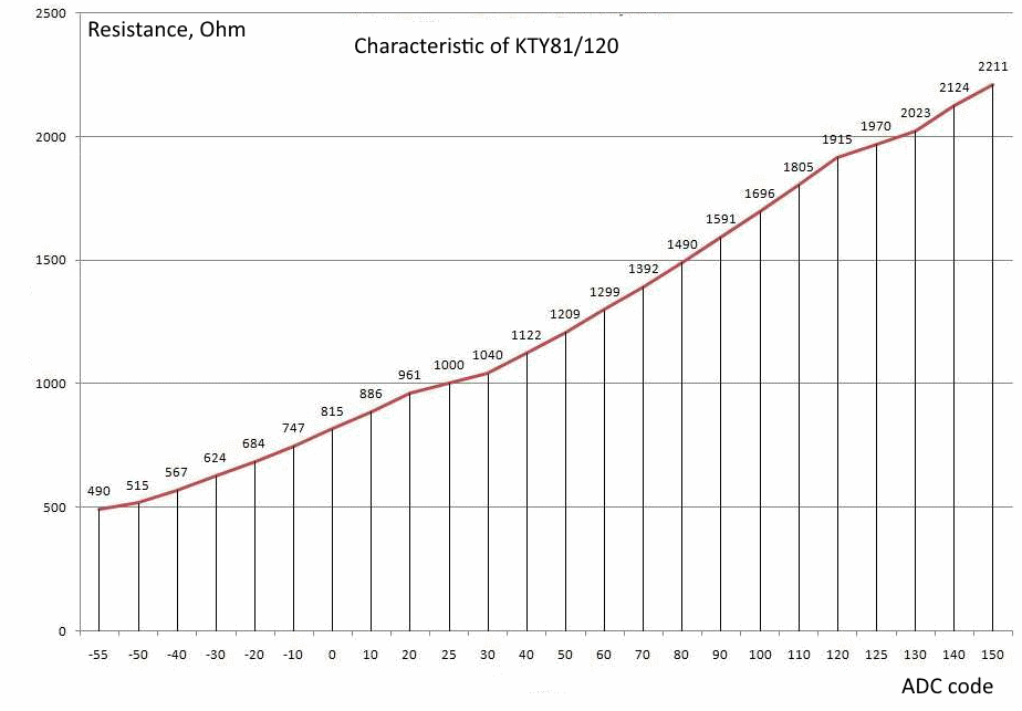
- characteristics (dependence of resistance on temperature) is given by a tabular way;
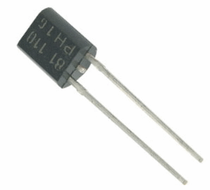
- the devices are made in the SOD70 package (as TO-92, only two pins).
To calculate the actual temperature, you must perform the following steps:
- measure the resistance of the temperature sensor;
- using a table characteristic to calculate the temperature (linearize the characteristic).
Measurement of active resistance in the Arduino system.
First of all, it is necessary to measure the resistance of the thermal sensor. Arduino ADC measures voltage. So it is necessary to convert the resistance into voltage. There are a large number of circuits with such a function. In our case, the best variant would be a simple voltage divider.
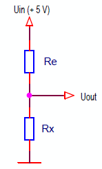
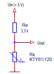
A voltage divider consisting of two resistors is connected between the 5 V power supply and the ground:
- Re - exemplary resistor;
- Rx - measured resistor.
The output voltage of the divider is:
Uout = Uin * Rx / (Re + Rx)
Hence:
Rx = Re / (Uin / Uout - 1)
This formula shows the main advantage of this method of measurement. The value of the supply voltage of the divider (Uin) is not important to us, its stability is not important, because the formula includes the ratio Uin / Uout.
And since the source of the reference voltage for the ADC is the 5 V supply, the ADC measures exactly the ratio Uin / Uout. It doesn't matter what the voltage is. We will not even set the resolution of the ADC in volts. We will define Uin / Uout as 1023 / N, where 1023 is the maximum ADC code value, N is the ADC code.
As a result, the formula for calculating the resistance will look like this:
Rx = Re / (1023 / N - 1),
N - ADC code.
The accuracy of measuring the resistance according to the divider circuit does not depend on the error of the supply voltage of the circuit, but is determined only by the resistance of the reference resistor Re.
However, this scheme is clearly non-linear characteristic and resolution. Let's define it on a specific example.
For the KTY81 / 120 sensor, the following parameters should be used:
| Minimum resistance at - 55 ° C | 490 Ohm |
| Maximum resistance at + 150 ° C | 2211 Ohm |
| Maximum permissible current at + 150 °C | 2 mA |
Choose an exemplary resistor with a resistance of 3300 Ohms. Then the current at + 150 °C will be equal to
5 V / (3300 + 2211) = 0.9 mA.
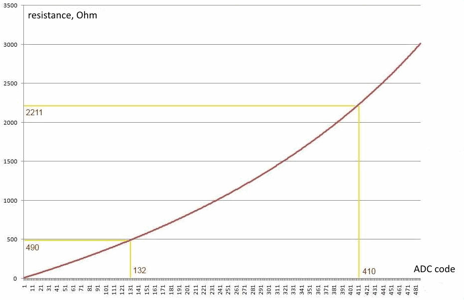
For clarity, I built two graphs in Excel. The first is the dependence of resistance on the ADC code.
The nonlinearity of the transformation is visible. If we use the KTY81 / 120 sensor, then it is required to measure the resistance in the range of 490 ... 2211 Ohm. The graph shows that this range corresponds to the ADC code of about 130 ... 410. You can calculate more precisely, but now this is not necessary. We have about 280 units of discretization of the ADC, which is quite enough.
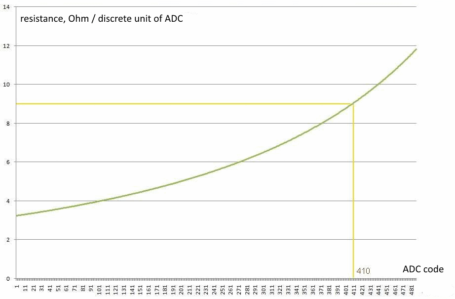
The second graph shows the dependence of the resistance corresponding to the unit of discreteness of the ADC on the ADC code. Those. It shows how the resolution of the resistance meter changes in the working range.
It can be seen that the worst value of the resolution of the resistance meter at the code 410, and is 9 Ohms. This corresponds to about 1 °C and we are quite satisfied.
As a result, the wiring diagram of the kty81/20 thermal sensor to the microcontroller looks like this.
For further calculations, we determine the exact limits of the operating range of the resistance meter.
N = Rx * 1023 / (Re + Rx)
| Limit | Sensor resistance, Rx |
ADC Code, N |
| Minimum temperature, - 55 °C | 490 ohm | 132 |
| Maximum temperature, + 150 ° C | 2211 Ohm | 410 |
Arduino thermometer project with temperature sensor KTY81/120.
We will develop a thermometer - a complete functional analogue of the device from the previous lesson, only using the KTY81 / 120 temperature sensor. Using of silicon sensor:
- extended the range of temperature measurement to - 55 ... + 150 ° C;
- allowed to place the sensor at a long distance (up to hundreds of meters) and use twisted pair cable as a communication line;
- reduced measurement accuracy to:
- ± 5 ° C in the range - 55… + 100 ° C
- ± 10 ° C in the range of + 100… + 150 ° C.
Measurement accuracy can be improved by the use of temperature sensors of type KTY81/110 to:
- ± 3.5 ° C in the range - 55… + 100 ° C;
- ± 8.5 ° C in the range of + 100… + 150 ° C.
The device:
- displays the temperature value on the LED indicator (standalone mode);
- transmits the temperature value to the computer;
- when using a high-level program from the previous lesson:
- displays the current temperature on the computer display;
- records the temperature change with a time resolution of 1 s;
- displays the temperature change in graphical form.
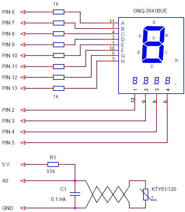
Schematic diagram of the thermometer.
Connect to Arduino Board:
- a 4 digit LED display;
- a temperature sensor KTY81/120.
All as in the previous lesson.
R1 is a model resistor. C1 - filters high-frequency noise, you can increase it to 1 microfarad. The use of electrolytic capacitors is undesirable. They have a high leakage current. The sensor is better to connect to the controller twisted pair.
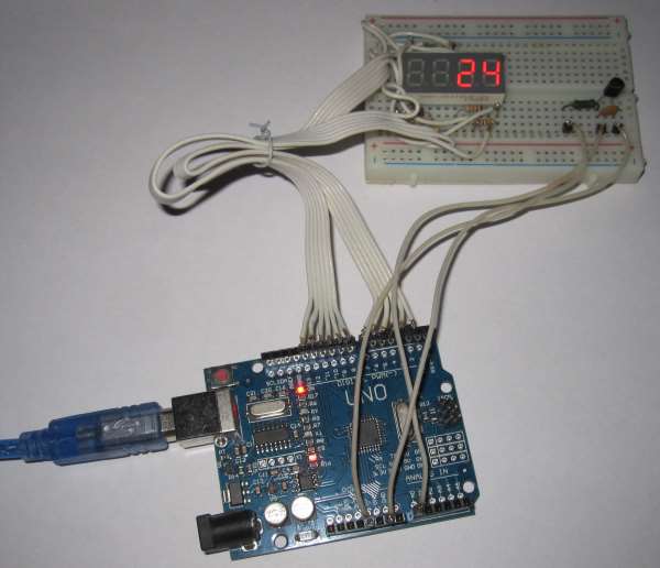
On the breadboard, the device looks like this.
The Arduino thermometer resident program.
The program should:
- to read the value of ADC;
- to average ADC codes to improve noise immunity;
- to calculate the temperature using the table characteristic of the KTY81 / 120 sensor;
- display the temperature value on the LED display in the format:
- sign;
- hundreds;
- tens;
- units ° C;
- to transmit the temperature value once per second to the computer.
The program is mostly similar to the program from the previous lesson. The changes affected only the principle of calculating the temperature.
Here is a sketch of the thermometer program.
// thermometer, sensor KTY81/120
#include <MsTimer2.h>
#include <Led4Digits.h>
#define MEASURE_PERIOD 500 // measurement time, * 2 ms
#define RO 3300 // resistance of the sample resistor, Ohm
#define MIN_ADC 132 // minimum value of the operating range of the ADC
#define MAX_ADC 410 // maximum value of the operating range of the ADC
#define POL_NUM 24 // number of poles of the characteristic
int sensTable[POL_NUM][2] = { // table of characteristics of the sensor
{-55, 490}, {-50, 515}, {-40, 567}, {-30, 624}, {-20, 684}, {-10, 747},
{0, 815}, {10, 886}, {20, 961}, {25, 1000}, {30,1040}, {40, 1122},
{50, 1209}, {60, 1299}, {70, 1392}, {80, 1490}, {90, 1591}, {100, 1696},
{110, 1805}, {120, 1915}, {125, 1970}, {130, 2023}, {140, 2124}, {150, 2211}
};
int codToTempTable[MAX_ADC - MIN_ADC +1]; // code to temperature conversion table
int timeCount; // measurement time counter
long sumA0; // ADC code summation variable
long avarageTemp; // average temperature value (sum of ADC codes, average value * 500)
boolean flagTempReady; // sign of temperature measurement readiness
int temperature; // calculated temperature, ° C
// type of display 1; pins of digits 5,4,3,2; pins of segments 6,7,8,9,10,11,12,13
Led4Digits disp(1, 5,4,3,2, 6,7,8,9,10,11,12,13);
void setup() {
MsTimer2::set(2, timerInterrupt); // set the timer interrupt period to 2 ms
MsTimer2::start(); // enable timer interrupt
Serial.begin(9600); // initialize port, speed 9600
//--------- preliminary calculation of temperature values -------------
// calculate the array codToTempTable[]
int codBeginPol=0; // segment beginning pole code
int codEndPol; // segment end pole code
float koeff; // coefficient for the interval between the poles
// pole cycle
for ( int p= 0; p < (POL_NUM-1); p++ ) {
// calculate the code for the next pole N= Rx * 1023 / (Re + Rx)
codEndPol = (int)(((float)sensTable[p+1][1] * 1023.) / (RO + (float)sensTable[p+1][1]) + 0.5) - MIN_ADC ;
codToTempTable[codEndPol] = sensTable[p+1][0]; // temperature for the next pole
// calculate the coefficient for the interval
koeff = (float)(sensTable[p+1][0] - sensTable[p][0]) / (float)(codEndPol - codBeginPol);
// temperature interpolation
for ( int n = codBeginPol; n < codEndPol; n++ ) {
codToTempTable[n]= sensTable[p][0] + (int)((float)(n - codBeginPol) * koeff +0.5 );
}
codBeginPol=codEndPol;
}
}
void loop() {
if ( flagTempReady == true ) {
flagTempReady= false;
// data is ready
// calculate temperature
temperature = (int)((float)avarageTemp / 500. + 0.5);
// check range
if (temperature < MIN_ADC) temperature= MIN_ADC;
if (temperature > MAX_ADC) temperature= MAX_ADC;
// read the final value from the array
temperature= codToTempTable[temperature - MIN_ADC];
// temperature output to the display
if (temperature >= 0) {
// temperature is positive
disp.digit[3]= 0; // minus not lit
disp.print((int)(temperature), 3, 1);
}
else {
// temperature is negative
disp.digit[3]= 0x40; // minus is displayed
disp.print((int)(temperature * -1), 3, 1);
}
// transmitt temperature to computer
Serial.println(temperature);
}
}
//-------------------------------------- interrupt handler 2 ms
void timerInterrupt() {
disp.regen(); // display regeneration
// measure the average temperature
timeCount++; // +1 averaging sample counter
sumA0+= analogRead(A0); // sum of the codes for channel A0 of the ADC
// check the number of averaging samples
if ( timeCount >= MEASURE_PERIOD ) {
timeCount= 0;
avarageTemp= sumA0; // overload of the average value
sumA0= 0;
flagTempReady= true; // sign of readiness result
}
}
Download the sketch of the Arduino Thermometer program at the link: sketch_25_1.
Led4Digits.h and MsTimer2.h libraries must be included. You can download the libraries from lesson 20 and lesson 10.
Calculation of temperature according to the characteristics of the sensor given by the table.
So, we have a table of the dependence of sensor resistance on temperature. It is taken from the materials at the link.
| Temperature, ° C | Resistance, Ohm |
| -55 | 490 |
| -50 | 515 |
| -40 | 567 |
| -30 | 624 |
| -20 | 684 |
| -10 | 747 |
| 0 | 815 |
| 10 | 886 |
| 20 | 961 |
| 25 | 1000 |
| 30 | 1040 |
| 40 | 1122 |
| 50 | 1209 |
| 60 | 1299 |
| 70 | 1392 |
| 80 | 1490 |
| 90 | 1591 |
| 100 | 1696 |
| 110 | 1805 |
| 120 | 1915 |
| 125 | 1970 |
| 130 | 2023 |
| 140 | 2124 |
| 150 | 2211 |
The dependence is specified in the form of 24 points (poles) with different steps of 5 or 10 ° C. We need to calculate the temperature from the ADC code. To calculate the values between the characteristic poles, linear interpolation should be used, i.e. connect points by straight lines.
Graphically, the interpolated characteristic of the KTY81/120 sensor looks like this.
To calculate the temperature, you can do the following steps:
- read the ADC code;
- calculate resistance;
- go over the poles of the characteristic and determine in which segment the measured resistance falls;
- by linear relationship between the poles to more accurately calculate the temperature.
But this method is very complicated and slow. Let's do it another way - we will calculate the temperature values for each ADC value in advance.
In the section on resistance measurement, we calculated that the operating range of the sensor in the ADC codes is 132 ... 410, i.e. 279 values. We need to calculate the correspondence of temperature to each code in this range (132 ... 410).
A preliminary calculation of the temperature values occurs once, when the program is started in the setup () function. As a result, an array is formed
int codToTempTable [MAX_ADC - MIN_ADC +1]; // code to temperature conversion table
Now, to calculate the measured temperature, it is enough to read the temperature value from this array at the address - the ADC code.
// read the final value from the array
temperature = codToTempTable [temperature - MIN_ADC];
Simple, fast operation.
The best variant is to calculate the codToTempTable [] array in advance by the high-level program and use it as an initialized array with the const modifier. Then there will be no preliminary calculations for temperature in the Arduino program. But I preferred to calculate it in the microcontroller program for clarity.
A few words about debugging the program. The calculations are quite complex, it is easy to make a mistake. Therefore, I did two tests:
- When forming the array codToTempTable[] through a serial port I output to the computer table with the values of the code, the pole, the coefficient of temperature. The temperature value in the poles compared with the table and made sure that between the poles the values are monotonous and approximately uniform.
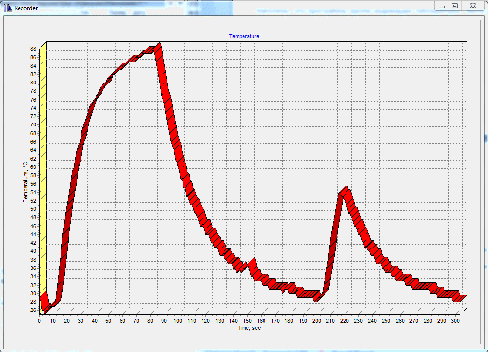
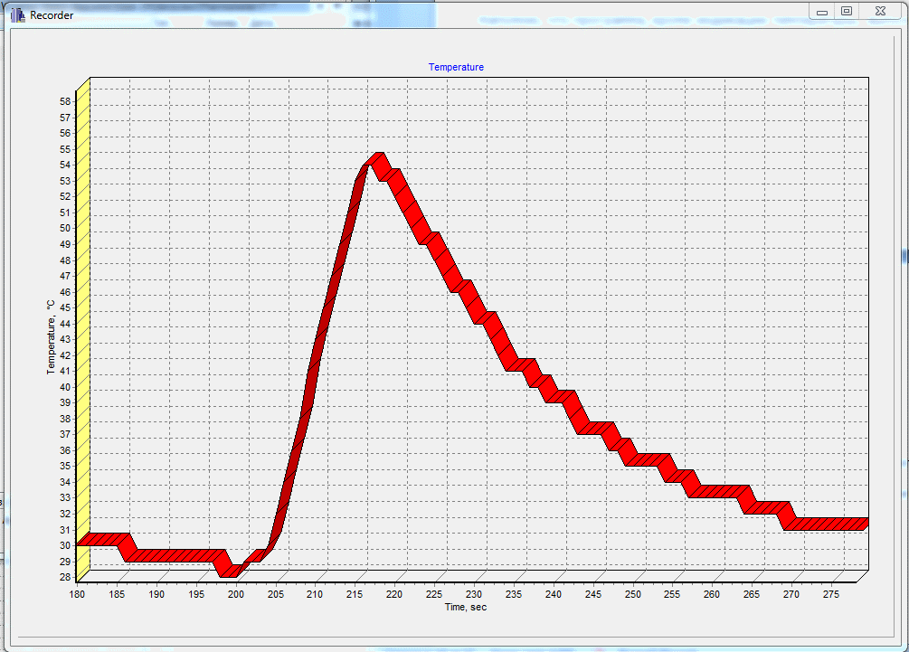
- In the program temporarily disabled the ADC and set the simulation of code changes per unit once per second. Using the recorder of the Thermometer program, I made sure that the change in the temperature value is monotonous.
Work the Arduino thermometer-recorder with a computer.
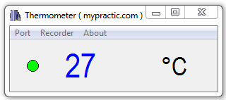
In standalone mode, the thermometer displays the temperature value on the LED indicators. When you connect your computer to the device, you can monitor the measured temperature using the Arduino IDE serial port monitor or the high-level Thermometer program.
This is a program from the previous lesson. You can download it from there.
The lesson describes in detail the installation and operation of the program Thermometer.
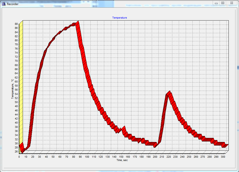
Let me remind you that the program, in addition to the temperature display, performs the function of a temperature recorder with a time resolution of 1 second.
The described principle of temperature measurement using silicon KTY81/120 sensors is quite applicable for other types of sensors with nonlinear resistance.
In the next lesson we will learn how to work with the DS18B20 temperature sensor, develop a thermometer with this sensor.

Hello Edward,
Could you explain what should be modified in code if NTC thermistor is used instead of PTC thermistor?
Thank You!
Hi!
It is necessary to change the algorithm for calculating the code-to-temperature conversion table.
It’s hard to tell right away. It may change the sequence of enumeration of poles from the last to the first enough.
// pole cycle
for ( int p= POL_NUM-1; p >=0; p– ) {
Hello,
I have made a polynoom calculation for the KTY83.(al most the same)
Here is the use code, it is small and works fine for the themperature between -30 and +50’Celcius.
You can use several sensors and libraries are not needed.
Here is the code:
Greeting from the Netherlands.
// Ruud van der Meer Netherlands Temp meting met KTY83 Dec 2020
// thermometer, sensor KTY83/110
// weerstand tegen plus 3300 Ohm 1%
int THERMISTORPIN ;
#define THERMISTORNOMINAL 1000
#define TEMPERATURENOMINAL 25
#define SERIESRESISTOR 3300
#define NUMSAMPLES 10
int samples[NUMSAMPLES];
float celcius;
void setup() {
Serial.begin(115200);
Serial.println(“Start Temperatuurmeting met PTC KTY83.”);
Serial.println(” “);
}
void loop() {
KTY83(A0);Serial.print(“Temperatuur A0 : “);Serial.print(celcius,1); Serial.println(” ‘C”);
delay(1000);
}
// Polynoom calculatie 2e graad afwijking tussen -30 en +50 < 0,2'C
void KTY83(int THERMISTORPIN){
uint8_t i; float measure;
for (i=0; i< NUMSAMPLES; i++) {samples[i] = analogRead(THERMISTORPIN);delay(10);}
measure = 0;
for (i=0; i< NUMSAMPLES; i++) {measure += samples[i];}
measure /= NUMSAMPLES;
//Serial.print(measure,0);Serial.print(" mVolt: ");
measure = 1023 / measure – 1;
measure = SERIESRESISTOR / measure;
//Serial.print("PTC KTY83 ");Serial.print(measure);Serial.println(" Ohm.");
float a = -0.000047;
float b = 0.2260;
float c = -153.8193;
celcius = a * pow(measure,2)+ (b * measure) + c;
//Serial.print(celcius,1);Serial.println(" Graden Celcius");
}
//end