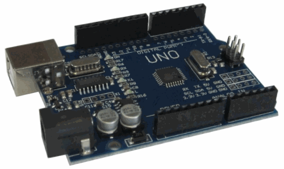
The article tells about Arduino UNO R3 controller, chosen for demonstration of lessons programs. Now it is not necessary to carefully study this information. I recommend that you skim it over to get an idea about the hardware of the system. In the future, this article can be used as reference information.
Previous lesson List of lessons Next lesson
As a controller for lessons, I chose the Arduino UNO R3 board. But nothing hinders the use of other boards.
The Arduino UNO board is probably the most popular among the developers of electronic products based on Arduino. It is ideal for debugging the software and hardware parts of devices during the development phase.
This is due to the presence of her:
- The interface converter, which allows you to connect the card directly to the USB ports of the computer.
- Sufficiently powerful stabilizers 3.3 and 5 V, which allows you to power your devices from the board.
- Wide range of supply voltages (6-20 V). The board can also be powered from the computer via USB.
- Connection of external devices takes place through the connectors, which is convenient during the development and debugging phase.
General information about the controller.
Arduino UNO R3 uses the microcontroller ATmega328. It has:
- 14 digital input / output ports (6 of them support PWM modulation mode);
- 6 analog inputs;
- clock frequency 16 MHz;
- USB port;
- power connector;
- In-circuit programming connector;
- Reset button.
The board has all the necessary components to ensure the operation of the microcontroller. It is enough to connect the USB cable to the computer and apply power. The microcontroller is installed in the socket, which makes it easy to replace it in case of failure.
Technical specifications.
| Type of microcontroller | ATmega328P |
| Supply voltage of microcontroller | 5 V |
| Recommended power supply voltage | 7 - 12 V |
| The maximum permissible supply voltage of the board | 6 - 20 V |
| Digital I / Os | 14 (of which 6 support PWM) |
| PWM Modulation Outputs | 6 |
| Analog inputs | 6 |
| Permissible current of digital outputs | 20 mA |
| Permissible output current 3.3 V | 50 mA |
| The size of flash memory | 32 KB (of which 0.5 KB is used by the loader) |
| RAM | 2 kB |
| The volume of non-volatile memory (EEPROM) | 1 KB |
| Clocking frequency | 16 MHz |
| Board length | 68.6 mm |
| Board width | 53.4 mm |
| Weight | 25 g |
Programming.
The controller can be programmed from the Arduino software integrated environment (IDE). Programming takes place under the management of a resident bootloader using the STK500 protocol. A hardware programmer is not required.
The microcontroller can be programmed via the connector for the ICSP in-circuit programmer without using the bootloader. The source code of the loader program is freely available.
The difference from other controllers Arduino.
Arduino UNO R3, unlike previous versions, does not use the USB-UART FTDI bridge to connect to the computer. This function is performed by the microcontroller ATmega16U2.
Supply system.
The UNO board can be powered from a USB port or from an external source. The power supply is automatically selected. An external power source can be an AC adapter or a battery. The adapter is connected through a connector with a diameter of 2.1 mm (central contact - positive). The battery is connected to the GND and Vin terminals of the POWER connector.
The voltage of the external power supply can be in the range of 6 - 20 V. But it is recommended to avoid the voltage drop below 7 V due to unstable operation of the device. It is also undesirable to increase the supply voltage by more than 12 V, because the stabilizer may overheat and fail. Those. the recommended voltage range is 7-12 V.
The following pins can be used to connect the power supply.
| Vin | Power board from an external power source. It is not connected to the 5 V power from the USB or the outputs of other stabilizers. Through this pin, you can receive power for your device if the board is powered by an adapter. |
| 5 V | Voltage stabilizer output of the board. It has a voltage of 5 V for any type of power supply. It is not recommended to feed the board through this pin, as the stabilizer is not used, which can lead to the microcontroller's failure. |
| 3 V 3 | Voltage 3.3 V from the voltage regulator on the board. The maximum permissible current consumption from this pin is 50 mA. |
| GND | Common wire. |
| IOREF | On the output information about the operating voltage of the board. The expansion board can read the signal value and switch to 5 V or 3.3 V power mode. |
Memory.
The microcontroller has three types of memory:
- 32 KB flash (FLASH);
- 2 KB of RAM (SRAM);
- 1 KB of non-volatile memory (EEPROM).
Inputs and outputs.
Each of the 14 digital pins can be used as an output or input. The voltage level at the pins is 5 V. It is recommended to limit the outflowing current and the inflowing current of each output to 20 mA. The maximum permissible value of this parameter is 40 mA. Each pin has an internal pull-up resistor with a resistance of 20-50 kΩ. The resistor can be disconnected programmatically.
Some pins can perform additional functions.
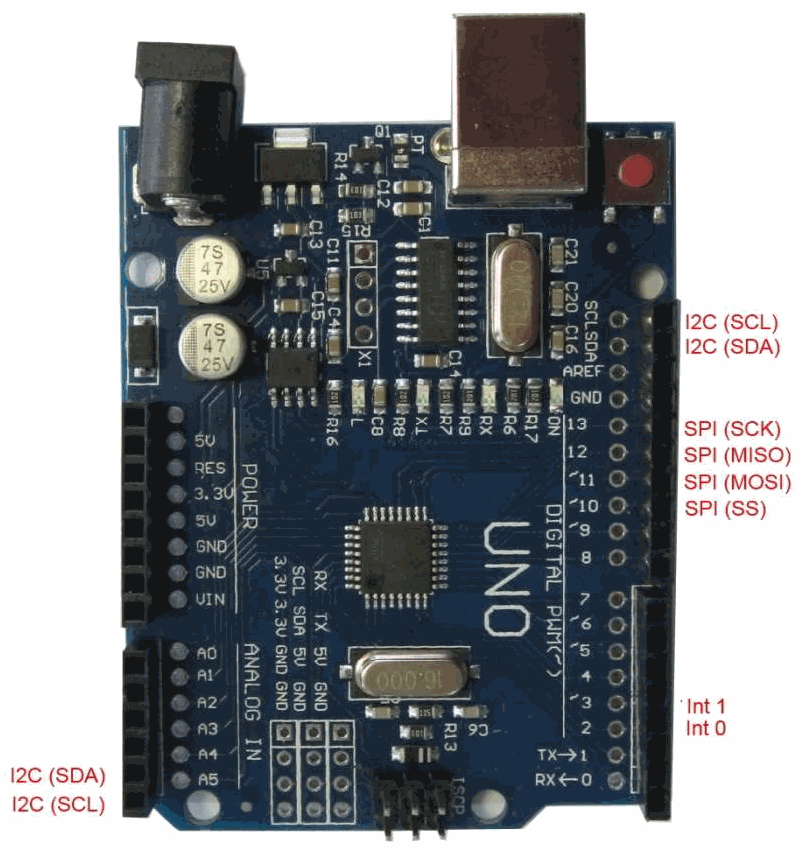
Serial interface: pins 0 (Rx) and 1 (Tx). Used to receive (Rx) and transmit (Tx) the serial data of logical TTL levels. These pins are connected to the data transfer terminals of the ATmega16U2 chip used as a USB-UART converter.
External interrupts: pins 2 and 3. These pins can be used as external interrupt inputs. Software can be set to interrupt at low level, positive or negative edge, or to change the signal level.
PWM: pins 3, 5, 6, 9, 10, 11. They can operate in PWM modulation mode with a resolution of 8 bits.
Serial interface SPI: pin 10 (SS), 11 (MOSI), 12 (MISO), 13 (SCK).
LED: pin 13. LED connected to pin 13. Lights when the output signal is high.
Interface TWI: output A4 or SDA and A5 or SCL. Communication interface TWI.
The Arduino UNO board has 6 analog inputs, labeled A0-A5. Resolution of analog to digital conversion 10 bits. By default, the input voltage is measured relative to the ground in the 0-5 V range, but can be changed with the AREF output and program settings.
Another 2 outputs of the board have functions:
AREF. Reference voltage of the microcontroller ADC.
RESET. A low level on this pin causes the microcontroller to reset.
Communication interfaces.
The Arduino UNO module has means for communicating with a computer, with another UNO board or with other microcontrollers. To do this, the board has a UART interface with logical levels of TTL (5 V), connected with pins 0 (RX) and 1 (TX). The ATmega16U2 chip on the board connects the UART interface to the computer's USB port. When connected to a computer port, a virtual COM port appears, through which computer programs work with Arduino. ATmega16U2 firmware uses standard USB-COM drivers and no additional drivers are required. For the Windows operating system, an appropriate .inf file is required. In the integrated environment of the Arduino software (IDE), a serial exchange monitor is enabled, which allows sending and receiving simple text data from the board. The board has RX and TX LEDs that indicate the status of the corresponding signals for communication via USB (but not for the serial interface on pins 0 and 1).
The ATmega328 microcontroller also supports I2C (TWI) and SPI communication interfaces.
Automatic (soft) reset.
In order that you do not have to press the reset button every time before downloading the program, the UNO card implements a hardware reset function initiated from the connected computer. One of the ATmega16U2 data flow control (DTR) signals is connected to the ATmega328 microcontroller reset terminal via a 0.1 μF capacitor. When the DTR signal goes low, a microcontroller reset pulse is generated. This solution allows you to download the program at the touch of a button from the integrated programming environment Arduino (IDE).
But such a function can lead to negative consequences. When the UNO card is connected to a computer with a Mac OS X or Linux operating system, the microcontroller will be reset each time the program is connected to the card. For half a second on the UNO card, the bootloader will be started. Despite the fact that the loader program ignores extraneous data, it can take several bytes from the packet immediately after the connection is established. If the program on the Arduino board requires that you receive any data on the first start, you must send the data with a delay of approximately 1 second after the connection.
On the UNO module, there is a track that can be cut to disable the automatic reset function. The track is marked with the inscription "RESET-EN". Automatic reset can also be disabled by connecting a 110 ohm resistor between the 5 V power line and the RESET pin.
Protect the USB port from overload.
In the Arduino UNO board, the power line from the USB interface is protected by a resetable fuse. If the current exceeds 500 mA, the fuse breaks the circuit until a short circuit is eliminated.
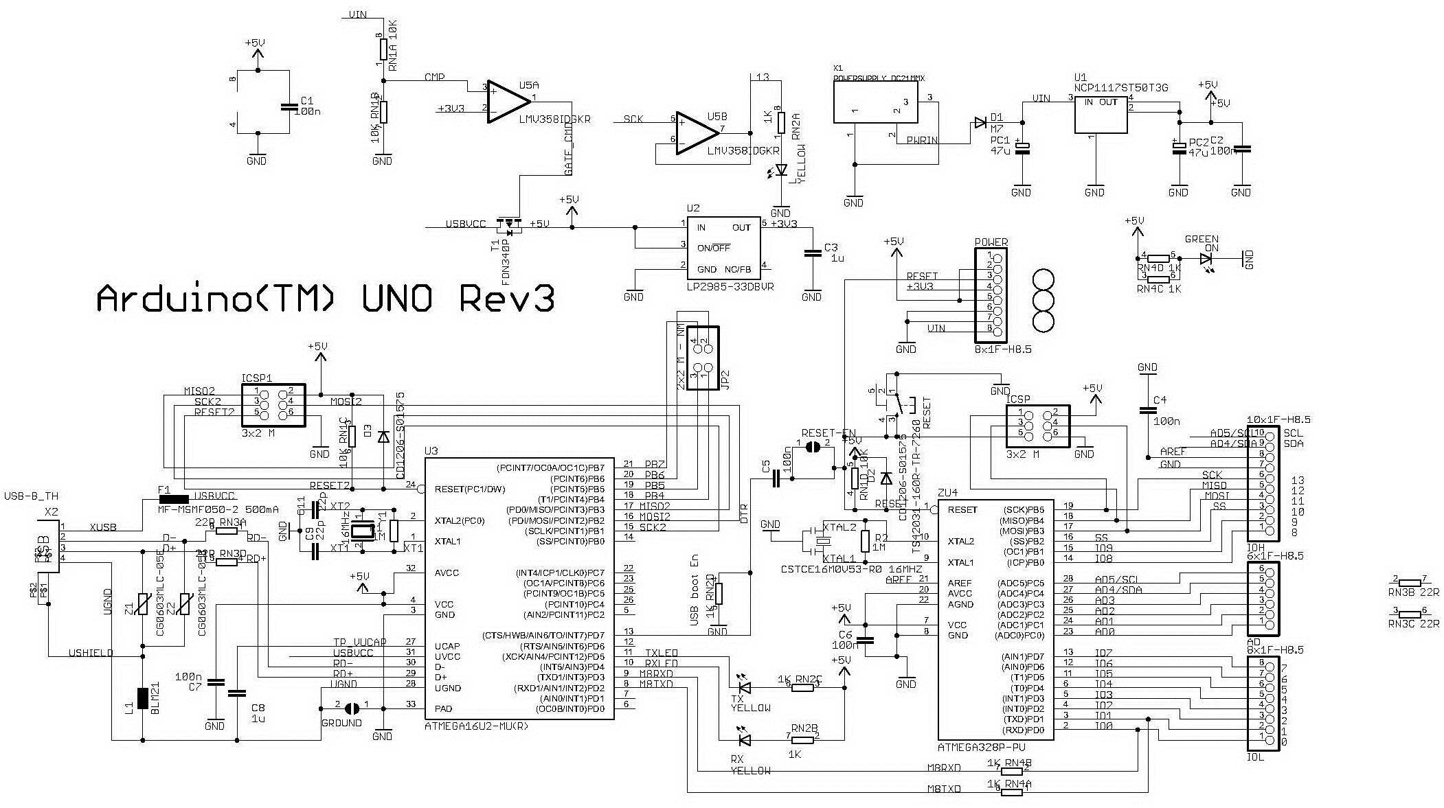
Arduino UNO controller circuit.


