In the lesson we will learn how to work with analog inputs of Arduino.
Previous lesson List of lessons Next lesson
Arduino UNO board contains 6 analog inputs intended for voltage measurement of signals. It is more correct to say that the 6 pins of the board can operate in the mode of both discrete pins and analog inputs.
These pins have numbers from 14 to 19. Initially, they are configured as analog inputs, and can be accessed via the names A0-A5. At any time they can be configured to the discrete inputs or outputs.
pinMode (A3, OUTPUT); // Set the discrete output mode for A3
digitalWrite (A3, LOW); // set low state at A3 output
To return to analog input mode:
pinMode (A3, INPUT); // set the analog input mode for A3
Analog inputs and pull-up resistors.
Pull-up resistors are connected to the pins of the analog inputs, as well as to the discrete pins. These resistors are turned on by the command:
digitalWrite (A3, HIGH); // switch on the pull-up resistor to the A3 input
The command must be applied to the pin configured in the input mode.
We must remember that the resistor can affect the level of the input analog signal. The current from the 5 V power supply, through a pull-up resistor, will cause a voltage drop across the internal resistance of the signal source. So it is better to turn off the resistor.
Analog-digital converter of Arduino board.
The actual measurement of the voltage at the inputs is made by an analog-to-digital converter (ADC) with 6 channels multiplexer. The ADC has a resolution of 10 bits, which corresponds to the code at the output of the converter 0 ... 1023. The measurement error is not more than 2 units of the lower digit.
To maintain maximum accuracy (10 bits) it is necessary that the internal resistance of the signal source does not exceed 10 kΩ. This requirement is especially important when using resistor dividers connected to the analog inputs of the board. The resistance of the resistors of the dividers can not be too large.
Functions for working with analog inputs.
int analogRead (port)
Reads the voltage value at the specified analog input. The input voltage range from 0 to the level of the reference voltage source (often 5 V) converts to code from 0 to 1023.
With a reference voltage of 5 V, the resolution is 5 V / 1024 = 4.88 mV.
It takes about 100 µs to convert.
int inputCod; // input voltage code
float inputVoltage; // input voltage, V
inputCod = analogRead (A3); // read the voltage at the A3 input
inputVoltage = ((float) inputCod * 5. / 1024.); // recalculate code to voltage (V)
void analogReference (type)
Sets the reference voltage for the ADC. It determines the maximum value of the voltage on the analog input that the ADC can correctly convert. The magnitude of the reference voltage also determines the code to voltage conversion factor:
Input voltage = ADC code * reference voltage / 1024.
Type can have the following values:
- DEFAULT - the reference voltage is equal to the controller supply voltage (5 V or 3.3 V). For Arduino UNO R3 - 5 V.
- INTERNAL - internal reference voltage of 1.1 V for boards with ATmega168 and ATmega328 controllers, for ATmega8 - 2.56 V.
- INTERNAL1V1 - internal reference voltage of 1.1 V for Arduino Mega controllers.
- INTERNAL2V56 - internal reference voltage of 2.56 V for Arduino Mega controllers.
- EXTERNAL - external reference voltage source, is connected to the AREF input.
analogReference (INTERNAL); // reference voltage is 1.1 V
It is recommended that an external reference voltage source be connected through a current-limiting resistor of 5 kΩ.
Dual channel voltmeter on Arduino.
As an example of using the functions of analog input let's create a project of a simple digital voltmeter on Arduino. The device must measure the voltage at the two analog inputs of the board, and transmit the measured values to the computer via the serial port. Using this project as an example, I will show the principles of creating simple measurement and information collection systems.
Let's decide that the voltmeter should measure the voltage in the range of not less than 0 ... 20 V and develop a wiring diagram for the inputs of the voltmeter to the Arduino UNO board.
If we set the reference voltage to 5 V, then the analog inputs of the board will measure the voltage in the range of 0 ... 5 V. And we need at least 0 ... 20 V. So we need to use a voltage divider.
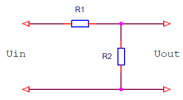
The voltage at the input and output of the divider are related by the relation:
U out = (U in / (R1 + R2)) * R2
Transfer ratio:
K = U out / U in = R2 / (R1 + R2)
We need a transfer ratio of 1/4 (20 V * 1/4 = 5 V).
To maintain maximum accuracy (10 bits) it is necessary that the internal resistance of the signal source does not exceed 10 kΩ. Therefore, we choose the resistor R2 equal to 4.22 kΩ. Calculate the resistance of the resistor R1.
0.25 = 4.22 / (R1 + 4.22)
R1 = 4.22 / 0.25 - 4.22 = 12.66 kΩ
I had the nearest nominal resistors with a resistance of 15 kΩ. With resistors R1 = 15 kΩ and R2 = 4.22:
5 / (4.22 / (15 + 4.22)) = 22.77 V.
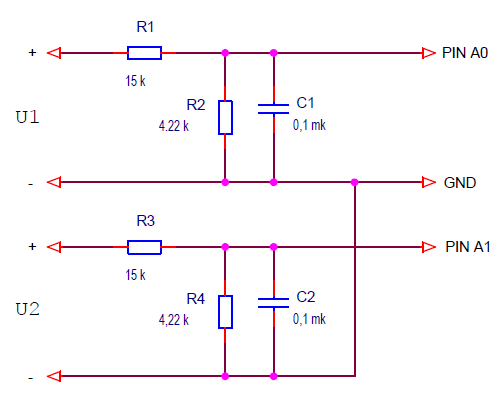
The circuit of the voltmeter based on Arduino will look like this.
Two voltage dividers are connected to analog inputs A0 and A1. The capacitors C1 and C2 together with the divider resistors form low-pass filters, which remove the high-frequency noise from the signals.
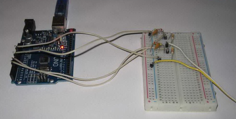
I assembled this circuit on a breadboard.
I connected the first input of the voltmeter to a regulated power supply, and the second to the power supply 3.3 V of the Arduino board. To control the voltage to the first input I connected a voltmeter. It remains to write the program.
The program for measuring voltage using the Arduino board.
The algorithm is simple. It is necessary:
- read the ADC code twice a second;
- recalculate it to voltage;
- send measured values via the serial port to a computer;
- display the received voltage values on a computer screen using the serial port monitor.
I give the sketch in full.
// voltage measurement program
// on analog inputs A0 and A1
#include <MsTimer2.h>
#define MEASURE_PERIOD 500 // time of measurement period
#define R1 15. // Resistor R1 Resistance
#define R2 4.22 // Resistor R2 Resistance
int timeCount; // time counter
float u1, u2; // measured voltages
void setup() {
Serial.begin(9600); // initialize the port, speed 9600
MsTimer2::set(1, timerInterupt); // timer interrupts, period 1 ms
MsTimer2::start(); // enable interrupt
}
void loop() {
// 500 ms period
if ( timeCount >= MEASURE_PERIOD ) {
timeCount= 0;
// read channel 1 code and recalculate to voltage
u1= ((float)analogRead(A0)) * 5. / 1024. / R2 * (R1 + R2);
// read channel 2 code and recalculate to voltage
u2= ((float)analogRead(A1)) * 5. / 1024. / R2 * (R1 + R2);
// data transfer through the serial port
Serial.print("U1 = "); Serial.print(u1, 2);
Serial.print(" U2 = "); Serial.println(u2, 2);
}
}
// interrupt processing 1 ms
void timerInterupt() {
timeCount++;
}
I will explain the line in which the ADC code is converted into voltage:
// read channel 1 code and recalculate to voltage
u1 = ((float) analogRead (A0)) * 5. / 1024. / R2 * (R1 + R2);
- Read ADC code: analogRead (A0).
- Explicitly converted to floating point format: (float).
- It is converted to voltage at the analog input: * 5. / 1024. A dot at the end of the numbers indicates that it is floating point numbers.
- Divider transfer ratio taken into account: / R2 * (R1 + R2).
Let's load the program into the board, launch the serial port monitor.
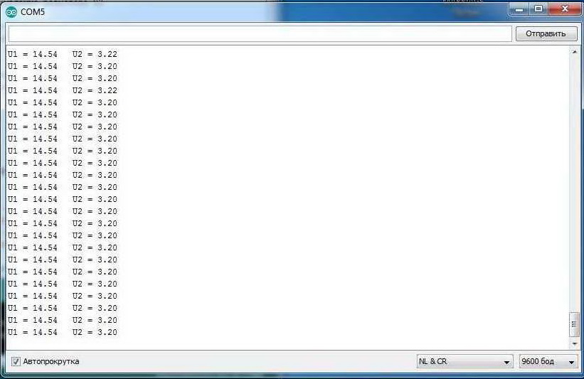
Two running columns of numbers show the values of the measured voltages. Everything is working.
Measurement of the average value of the signal.
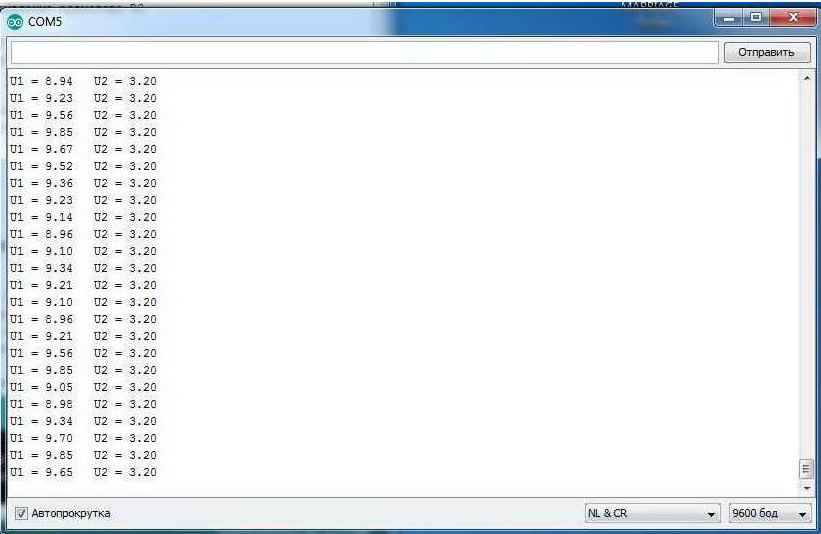
Let's connect the first channel of our voltmeter to a voltage source with a high level of ripple. We will see this picture on the monitor.
The voltage values of the first channel on the monitor screen all the time twitch, jump. And the readings of the control voltmeter are quite stable. This is because the reference voltmeter measures the average value of the signal, while the Arduino board reads individual samples every 500 ms. Naturally, the time of reading the ADC falls into different points of the signal. And with a high level of pulsations, the amplitude at these points is different.
In addition, if the signal is read by individual rare samples, then any impulse noise can introduce a significant error in the measurement.
The solution is to make several frequent samples and average the measured value. For this we need:
- in the interrupt handler, read the ADC code and summarize it with the previous samples;
- count the averaging time (the number of averaging samples);
- when a specified number of samples is reached, save the total value of the ADC codes;
- to obtain the average value, divide the sum of ADC codes by the number of averaging samples.
The task of the textbook of mathematics grade 8. Below is a sketch that implements such an algorithm.
// program for measuring the average voltage
// on analog inputs A0 and A1
#include <MsTimer2.h>
#define MEASURE_PERIOD 500 // time of measurement period
#define R1 15. // Resistor R1 Resistance
#define R2 4.22 // Resistor R2 Resistance
int timeCount; // time counter
long sumU1, sumU2; // variables for summing ADC codes
long averageU1, averageU2; // sum of ADC codes (average * 500)
boolean flagReady; // flag of readiness of measurement data
void setup() {
Serial.begin(9600); // initialize the port, rate 9600
MsTimer2::set(1, timerInterupt); // timer interrupts, period 1 ms
MsTimer2::start(); // enable interrupt
}
void loop() {
if ( flagReady == true ) {
flagReady= false;
// convert to voltage and transfer to computer
Serial.print("U1 = ");
Serial.print( (float)averageU1 / 500. * 5. / 1024. / R2 * (R1 + R2), 2);
Serial.print(" U2 = ");
Serial.println( (float)averageU2 / 500. * 5. / 1024. / R2 * (R1 + R2), 2);
}
}
// interrupt processing 1 ms
void timerInterupt() {
timeCount++; // +1 averaging sample counter
sumU1+= analogRead(A0); // summation of ADC codes
sumU2+= analogRead(A1); // summation of ADC codes
// check the number of averaging samples
if ( timeCount >= MEASURE_PERIOD ) {
timeCount= 0;
averageU1= sumU1; // overload average
averageU2= sumU2; // overload average
sumU1= 0;
sumU2= 0;
flagReady= true; // flag measurement result is ready
}
}
Added to the formula for converting the ADC code to voltage is / 500 - the number of samples. Load, launch the port monitor (Cntr + Shift + M).
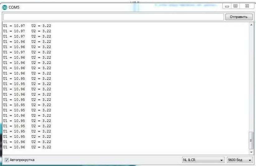
Now, even with a significant level of pulsations, the readings change only for hundredths. This is only because the voltage is not stabilized.
The number of samples must be chosen, considering:
- the number of samples determines the measurement time;
- the larger the number of samples, the less interference will be.
The main source of interference in analog signals is the power network of 50 Hz. Therefore, it is desirable to choose averaging time a multiple of 10 ms - the network half period with a frequency of 50 Hz.
Optimization of calculations.
Calculations with floating point simply devour the resources of an 8-bit microcontroller. Any operation with floating point requires denormalization of the mantissa, operation with a fixed comma, normalization of the mantissa, correction of the order ... And all operations are with 32 bit numbers. Therefore it is necessary to minimize the use of floating-point calculations. How to do this, I will tell in the following lessons, but let's at least optimize our calculations. The effect will be significant.
In our program, the conversion of the ADC code into voltage is written as follows:
(float) avarageU1 / 500. * 5. / 1024. / R2 * (R1 + R2)
How many calculations are there, and everything is floating point. But most of the calculations are operations with constants. Part of the line:
/ 500. * 5. / 1024. / R2 * (R1 + R2)
we can calculate on the calculator and replace with one constant. Then our calculations can be written as:
(float) avarageU1 * 0.00004447756
Smart compilers themselves recognize calculations with constants and count them at compile time. I had a question about how smart the Andruino compiler is. Decided to check.
I designed a short program. It performs a cycle of 10,000 passes, and then transmits to the computer the execution time of the 10,000 cycles. Those. It allows you to see the execution time of the operations placed in the body of the loop.
// calculation optimization test
int x= 876;
float y;
unsigned int count;
unsigned long timeCurrent, timePrev;
void setup() {
Serial.begin(9600);
}
void loop() {
count++;
// y= (float)x / 500. * 5. / 1024. / 4.22 * (15. + 4.22);
// y= (float)x * 0.00004447756;
if (count >= 10000) {
count= 0;
timeCurrent= millis();
Serial.println( timeCurrent - timePrev );
timePrev= timeCurrent;
}
}
In the first case, when in loop(), floating point operations are commented out and not executed, the program gave a result of 34 ms.
Those. 10,000 empty loops are executed in 34 ms.
Then I opened the line:
y = (float) x / 500. * 5. / 1024. / 4.22 * (15. + 4.22);
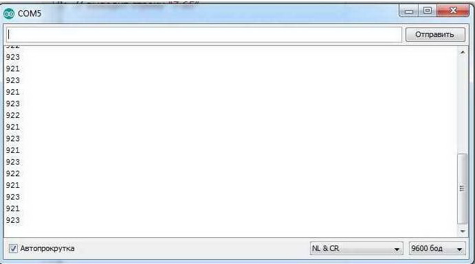
which repeats our calculations. Result 10,000 passes for 922 ms or
(922 - 34) / 10 000 = 88.8 μs.
Those. This line of floating point calculations requires 89 µs to be executed. I thought it would be more.
Now I have closed this line with a comment and opened the following one, with multiplication by a previously calculated constant:
y = (float) x * 0.00004447756;
Result 10,000 passes for 166 ms or
(166 - 34) / 10 000 = 13.2 μs.
Awesome result. We saved 75.6 μs per line. We performed it almost 7 times faster. We have 2 such lines. But there can be much more of them in the program.
Conclusion - calculations with constants should be made on the calculator and used in the programs as ready-made coefficients. The Arduino compiler does not compute them at compile time. In our case, you need to do this:
#define ADC_U_COEFF 0.00004447756 // coefficient of conversion of the ADC code into voltage
Serial.print ((float) avarageU1 * ADC_U_COEFF, 2);
The best option is to transfer the ADC code to the computer, and with it all the floating point calculations. In this case, a specialized program should receive data on the computer. The port monitor from the Arduino IDE will not work
I will talk about other ways to optimize Arduino programs in future lessons as needed. But without solving this issue, it is impossible to develop complex programs on an 8-bit microcontroller.
The site will have another lesson (lesson 65) dedicated to the measurement of analog signals. It will discuss the work of the ADC in the background.
In the next lesson we will learn how to work with an internal EEPROM, will talk about data integrity monitoring.

