The lesson describes the Arduino board UART serial interface, the library for working with it, and the use of the UART port for debugging programs.
Previous lesson List of lessons Next lesson
The Arduino IDE does not have a debugger, which creates certain problems in finding program code errors.
There are always mistakes when developing programs. Formal errors are detected during compilation. Finding algorithmic and computational errors is much more difficult.
The Internet describes many ways to debug programs that use additional libraries, programs, hardware adapters. But the main function of debugging is to see the state of the program, to know the value of variables. This can be done by transmitting the necessary information to the computer via a serial interface. Physical connection of the Arduino board to a computer via a USB cable always exists. The Arduino IDE has a serial port monitor that allows you to receive and send exchange data with the board. You can transfer to the computer any information about the state of the program and display it on the monitor. This way of debugging suits me perfectly. Only instead of the Arduino IDE monitor, I sometimes use my programs that display data in a convenient form.
Of course, the UART interface in Arduino can be used to communicate with other controllers or peripheral devices, but so far we are interested in it from the point of view of communication with a computer.
Serial UART interface.
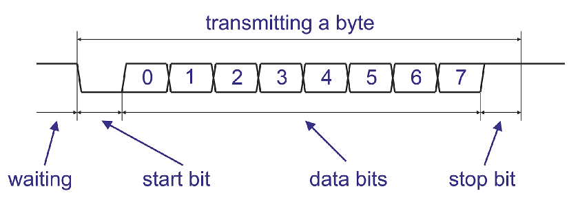
The UART is a Universal Asynchronous Receiver-Transmitter. UART data is transmitted by a serial code in the following format.
Each bit is transmitted at regular intervals. The transmission time of one bit is determined by the transmission rate. The transmission rate is indicated in baud (bits per second). In addition to the data bits, the UART interface inserts synchronization bits into the stream: start and stop. Thus, to transfer a byte of information requires 10 bits, not 8. The error of the time intervals for the transmission of bits should be no more than 5% (no more than 1.5% is recommended).
I describe the most common format. There are variants with a different number of data bits, synchronization bits, a parity bit, etc. But these formats are rarely used. The main thing to remember:
- in inactive mode, the UART output is in a high state;
- transmission of a byte begins with a start bit (low level);
- byte transmission ends with a stop bit (high level);
- data is transmitted with the low bit forward;
- 10 bits are required to transfer a byte;
- transmission time of one byte is calculated based on the transmission rate and the number of bits (10).
The following standard UART transmission rates are often used.
| Transmission rate, baud |
Transmission time of one bit, μs | Transmission time byte, μs |
| 4800 | 208 | 2083 |
| 9600 | 104 | 1042 |
| 19200 | 52 | 521 |
| 38400 | 26 | 260 |
| 57600 | 17 | 174 |
| 115200 | 8,7 | 87 |
Information is exchanged via UART in duplex mode, i.e. data transmission can occur simultaneously with recieving. For this, there are two signals in the UART interface:
- TX - output for data transmission;
- RX - input for receiving data.
When two UART devices are connected, the TX output of one device is connected to the RX input of the other. And the TX signal of the second UART is connected to the RX input of the first one.
Serial UART interface in Arduino.
Any Arduino board has at least one hardware UART serial interface. The Arduino Mega and Arduino Due boards each have three ports.
When I use the expression hardware interface, I emphasize that there is an electronic node in the controller, into the register of which the program only loads bytes for transmission, and the formation of exchange signals and all other operations is done by this node. Software data transfer via the UART protocol can also be implemented. In this case, all signals are generated by the program. Of course, it takes CPU resources.
Arduino UNO board has one UART port, the signals of which are connected to pins 0 (RX signal) and 1 (TX signal). The signals have logical TTL levels (0 ... 5 V). Through these pins (0 and 1), you can connect another device with a UART interface to the board.
In addition to the function of communicating with other controllers, the UART port of the Arduino UNO board is used to download a program to the controller from a computer. To do this, the corresponding signals of the ATmega16U2 chip - a USB / UART interface converter are connected to the same signals (RX and TX). The converter IC is connected through 1 kΩ resistors.
Fragment of the Arduino UNO R3 board layout.
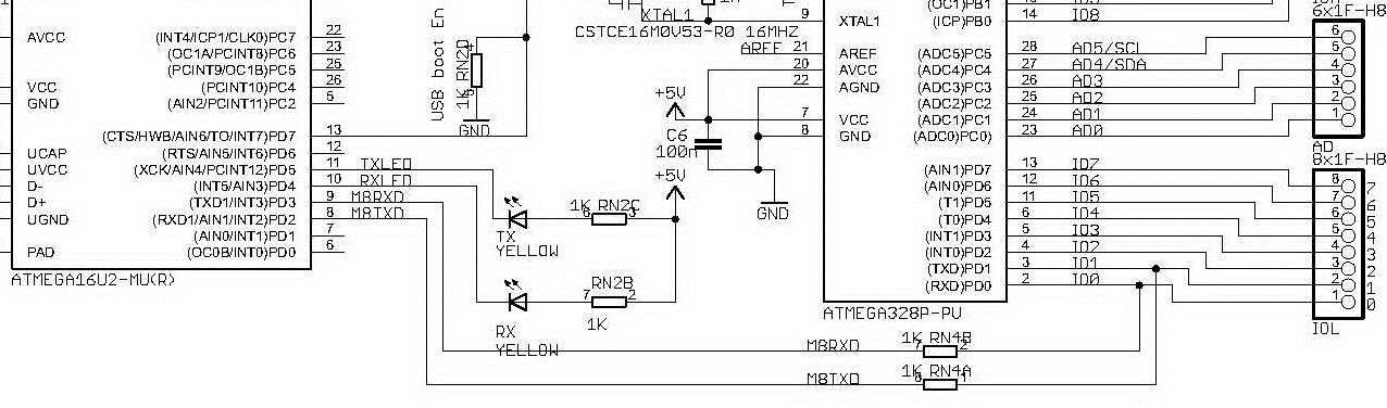
Thus, with free outputs 0 and 1 of the Arduino board, the signals from the ATmega16U2 microcircuit are fed to the ATmega328 controller. And if an external UART device is connected to the board, then its signals will have priority, since ATmega16U2 is connected through resistors.
The ATmega16U2 interface converter allows you to connect the Arduino board to a computer via a USB port. The driver must be installed on the computer. It creates a virtual COM port on the computer. Through it the exchange takes place.
It is important to understand, despite the fact that the board is connected to the computer via the USB port, all programs exchange data through the virtual COM port, unaware that the port is virtual.
Serial library for working with Arduino UART.
To work with hardware UART controllers in Arduino, there is a built-in class Serial. It is designed to control the exchange of data through the UART. Before I talk about the functions of the Serial class, I want to explain the difference in the format of the exchange data.
Through the serial interface, data is always transmitted in binary code. The question is how to interpret this data, how to perceive it. For example, the binary code “01000001” (decimal 65) is transmitted. How to display it on the screen? The number 65 can be transmitted and ”65” should be displayed on the screen. Or maybe it is the code of the letter "A", then on the screen you need to write "A". Just need to know in what format the data is transmitted.
In the Serial class, data can be transmitted in two formats:
- as a binary code;
- as ASCII characters.
For example, the serial port monitor in the Arduino IDE program accepts data as ASCII text. In order for it to display the number “65” on the computer screen, it is necessary to transmit the character codes “6” and “5”. And the code “65” will be displayed by the monitor as symbol “A”.
The main functions of the Serial class.
void begin (long speed)
The function enables the operation of the UART port and sets the baud rate (bits per second). To set the data transfer rate, it is recommended to use the standard values (table in the “Serial UART” section).
Serial.begin (38400); // initialization of the port, speed 38400 baud
void end (void)
The method disables the UART port, frees the RX and TX pins.
Serial.end (); // close the UART port
int available (void)
The method returns the number of bytes received by the serial port and written to the buffer. Serial port buffer can store up to 64 bytes. In the case of an empty buffer, returns 0.
int n;
n = serial. available (); // in n number of bytes received
int read (void)
Returns the next byte from the serial buffer. If the buffer is empty, returns the number - 1 (0xffff).
receiveByte = Serial.read (); // read byte from buffer
void flush (void)
Waits for the end of data transfer from the serial port buffer.
Serial.flush (); // waiting for the end of the transfer
print ()
Outputs data via the serial port UART in the form of ASCII characters. The function has various call forms for different formats and data types.
| print(char d) | If the argument is a char type it outputs to the port the character code.
char d = 83; |
| print(byte d)
|
If the argument is a byte type, then displays the string with a code of the number.
byte d = 83; |
| print(int d) | If the argument is an integer type, then displays a string with a decimal number
int d = 83; |
| print(float) | Real types are displayed in ASCII characters, two digits after the decimal point.
float d = 7.65432; |
| print(* str) | If the argument is a pointer to an array or string, then the array or string is transmited byte-by-byte to the port.
char letters [3] = {65, 66, 67}; |
| print(int d, DEC) | Displays an ASCII string - a decimal representation of the number.
int d = 83; |
| print(int d, HEX) | Displays an ASCII string — a hexadecimal representation of the number.
int d = 83; |
| print(int d, OCT) | Displays an ASCII string — an octal representation of the number.
int d = 83; |
| print(int d, BIN) | Displays an ASCII string - a binary representation of the number.
int d = 83; |
| print(int d, BYTE) | Displays the code of the number low byte.
int d = 0x0283; |
| print(float d, N) | For real numbers, the parameter N sets the number of digits after the decimal point.
Serial.print (7.65432, 0); // displays the string “7” |
println ()
Outputs data through the UART serial port in the form of ASCII characters with the addition of newline characters (\ r, code 13) and (\ n, code 10). The following message will be displayed on the new line. The rest is similar to the print() function.
int d = 83;
Serial.print (d, DEC); // display line “83”
Serial.println (d, DEC); // display the string “83 \ r \ n”
int write ()
Outputs binary data through the serial port UART. Returns the number of bytes transferred.
| int write(val) | Sends a byte.
Serial.write (83); // sends byte 83 |
| int write(str) | Sends a string as a sequence of bytes.
int bytesNumber; // number of bytes |
| int write(* buf, len) | Sends bytes from an array, the number of bytes is len.
char buf = “String”; |
int peek (void)
Returns the next byte from the serial buffer without deleting it from the buffer. If the buffer is empty, then returns -1. The function returns the same value as the read() function.
int readBytes (* buf, len)
Reads bytes arriving in the serial port and writes them to the buffer. Stops after receiving a specified number of bytes or in the case of a timeout. Returns the number of bytes received. The timeout is set by the setTimeout() function.
setTimeout (long time)
Sets the timeout time for the readBytes() function. The time is specified in ms, by default it is 1000 ms.
void serialEvent ()
Called when data arrive at the serial port. In fact - an interrupt on receiving data from the serial port.
serialEvent () {
// code for processing port data
}
Using the Serial class.
The Serial class is a built-in class. For him, do not need to search for the library and include it. In order to use the UART, it is enough in setup() to enable the port and set the rate:
void setup() {
Serial.begin(9600); // initialize port, rate 9600
}
Now you can transfer data using the print() or write() function.
Serial.println("Message to monitor"); // message to the serial monitor
If several bytes are output through the port, the Serial class writes them to the program buffer and sequentially transfers the data to the UART controller as it is transmitted.
Here is a program that displays a message and a pass number to the serial monitor every second.
unsigned int i=0;
void setup() {
Serial.begin(9600); // initialize port, rate 9600
}
void loop() {
Serial.print("Cycle: ");
Serial.println(i);
i++;
delay(1000);
}

When data arrives at the UART input, the Serial class writes them to the software buffer. To read the data from the buffer, you must first check whether they are there.
if (Serial.available()> 0) {
// there is data
Here is a program that reads a byte from the serial port and sends it to the port. Those. Everything we enter in the serial monitor should appear in the monitor window for the received data.
unsigned int i=0;
void setup() {
Serial.begin(9600); // initialize port, rate 9600
}
void loop() {
if( Serial.available() > 0 ) {
// there is data
Serial.write(Serial.read());
}
}

Debugging programs using the serial port of the Arduino.
The principle of debugging is simple.
- With the help of the serial port and the functions of the Serial class we can transfer information about the state of the program to the computer.
- With the help of the Arduino IDE serial port monitor or another program, we can see this data on a computer screen.
- The same software tools can transfer data to the Arduino program and affect its operation.
For example, we check the operation of buttons and functions of processing signals of buttons. In the program block, which is performed by pressing the buttons, we insert the command to send the message to the computer.
For the buttons connected according to the scheme of the previous lesson, the sketch of the program looks like this.
// debugging buttons using the UART port
#include <MsTimer2.h>
#include <Button.h>
#define BUTTON_1_PIN 12 // button 1 is connected to pin 12
#define BUTTON_2_PIN 11 // button 2 is connected to pin 11
Button button1(BUTTON_1_PIN, 20); // create an object button 1
Button button2(BUTTON_2_PIN, 20); // create an object button 2
void setup() {
Serial.begin(9600); // initialize the port, rate 9600
MsTimer2::set(2, timerInterupt); // set the timer interrupt with a period of 2 ms
MsTimer2::start(); // enable interrupt
}
void loop() {
// check button 1
if ( button1.flagClick == true ) {
button1.flagClick= false;
Serial.println("Button 1 was pressed"); // message for the monitor
}
// check button 2
if ( button2.flagClick == true ) {
button2.flagClick= false;
Serial.println("Button 2 was pressed"); // message for the monitor
}
}
// interrupt handling
void timerInterupt() {
button1.scanState(); // call the button 1 signal processing method
button2.scanState(); // call the button 2 signal processing method
}
Now, for each press of button 1, the message “Button 1 was pressed” will be transmitted to the computer via the serial port of the Arduino board, and by pressing button 2, the message “Button 2 was pressed”.
To see these messages, you must start the port monitor: Tools -> Serial Monitor. Now you can click on the buttons and see the reaction in the monitor window.

It is only necessary that the exchange rates be the same in the program and the monitor (I have 9600 baud).
You can also transfer variable values, calculation results, modes, etc. In subsequent lessons in almost every program, we will use a serial port to monitor the status of the program.
In the next lesson we will learn to read the values of signals on the analog inputs of the Arduino board.
Very clear explanation of UART in Arduino. Thanks!