We learn how to work with timer interrupts. We write a simple program with parallel processes.
Previous lesson List of lessons Next lesson
In a real program, you need to perform many actions at the same time. In the introduction, I gave an example of a Peltier module controller program for a fridge. I will list what actions it performs:
| Operation | Cycle Time |
| Interrogates 3 buttons, processes signals from them for debounce of button contacts | 2 ms |
| Regenerates data of seven-segment LED indicators | 2 ms |
| Generates control signals for 2 DS18B20 temperature sensors and reads data from them. Sensors have a 1-wire serial interface. | 100 μs for each bit, 1 sec per whole reading cycle |
| Reading analogue values of current and voltage on the Peltier element, supply voltage. | 100 μs |
| Digital filtering of analog current and voltage values. | 10 ms |
| Peltier element power calculation | 10 ms |
| PID (proportional-integral-differential) regulator for stabilizing current and voltage. | 100 μs |
| Power regulator. | 10 ms |
| Temperature regulator. | 1 sec |
| Protective functions, data integrity control. | 1 sec |
| Management, the general logic of the system. | 10 ms |
All these operations are performed cyclically, all have different periods of cycles. Neither of them can be suspended. Any, even brief, change in the time of the operation period will lead to trouble: a significant measurement error, incorrect operation of stabilizers, flickering of indicators, an unstable reaction of pressing buttons, etc.
There are several parallel processes in the refrigerator controller program that perform all of these actions, each in a loop with its own period time.
Parallel processes are processes whose actions are performed simultaneously.
In previous lessons we created a class for the button object. We said that this is a class for processing a signal in a parallel process. For its normal operation it is necessary to call the function (method) of signal processing in a cycle with a regular period (we chose a time of 2 ms). And then, flags showing the current state of the button or signal are available anywhere in the program.
In one cycle, we put the code for processing the state of the buttons and control the LEDs. At the end of the cycle, we set the delay function delay(2). But, the time to execute a program in a cycle changes the total cycle time. And the cycle period is clearly not equal to 2 ms. In addition, during the execution of the delay() function, the program hangs and cannot perform any other actions. In a complex program we get complete chaos.
The solution is to call the function of processing the state of the button in the interrupt from the hardware timer. Every 2 ms the main program loop should be interrupted, the signal from the button should be processed and control returned to the main loop to the code where it was interrupted. A short time for processing a button signal will not significantly affect the execution of the main loop. Those. button processing will occur in parallel, unnoticed by the main program.
A hardware timer interrupt.
A hardware interrupt is a signal that reports some event. Upon its arrival, the execution of the program is suspended, and control passes to the interrupt handler. After processing, the control returns to the interrupted program code.
From the point of view of the program, an hardware interrupt is a function call on an external, not directly related to the program code, event.
The timer interrupt signal is generated cyclically, with a specified period time. It is formed by a hardware timer - a counter with logic, which resets its code when it reaches a certain value. By programmatically setting the code for the reset logic, we can set the time of the timer interrupt period.
Setting the mode and time of the Arduino timer period is done through the hardware registers of the microcontroller. If you wish, you can figure out how to do it. But I offer a simpler variant - using the MsTimer2 library. The setting of the timer mode does not happen often, and therefore, the use of library functions will not slow down the program.
MsTimer2 library .
The library is designed to configure a hardware interrupt from the Timer 2 of microcontroller. It has only three functions:
MsTimer2 :: set (unsigned long ms, void (* f) ())
This function sets the time of the interruption period in ms. With this period, the interrupt handler f will be called. It must be declared as void (returns nothing) and have no arguments. * f is a function pointer. Instead, write the name of the function.
MsTimer2 :: start ()
The function enables timer interrupts.
MsTimer2 :: stop ()
The function disables timer interrupts.
Before the function name you should write MsTimer2 ::, since the library is written using the namespace directive.
To install the library, copy the MsTimer2 directory to the libraries folder in the working folder of the Arduino IDE. Then launch the Arduino IDE program, open Sketch -> Include Library and make sure that the MsTimer2 library is in the list of libraries.
You can download the MsTimer2 library in a zip archive using this link MsTimer2.zip. To install the library, unpack it.
A simple program of button signal parallel processing.
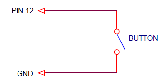
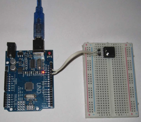
Now we will write a simple program with one button and the LED from lesson 6. One button is connected to the Arduino board according to the scheme:
It looks like this:
For each pressing the button, the LED on the Arduino board changes its state. It is necessary that the Button and MsTimer2 libraries be installed.
// sketch_10_1 Lesson 10
// Pressing the button changes the state of the LED
#include <MsTimer2.h>
#include <Button.h>
#define LED_1_PIN 13 // LED is connected to pin 13
#define BUTTON_1_PIN 12 // button connected to pin 12
Button button1(BUTTON_1_PIN, 15); // create object - button
void setup() {
pinMode(LED_1_PIN, OUTPUT); // determine the output for the led as an output
MsTimer2::set(2, timerInterrupt); // set the timer interrupt period 2 ms
MsTimer2::start(); // enable timer interrupt
}
void loop() {
// LED control
if ( button1.flagClick == true ) {
// was button click
button1.flagClick= false; // reset sign
digitalWrite(LED_1_PIN, ! digitalRead(LED_1_PIN)); // LED state inversion
}
}
// interrupt handler
void timerInterrupt() {
button1.scanState(); // call the method of waiting for a stable state for button
}
In the setup() function, we set the timer interrupt cycle time 2 ms and specify the name of the interrupt handler timerInterrupt. The signal processing function of the button button1.scanState() is called in the timer interrupt handler every 2 ms.
Thus, we process the button state by a parallel process. And in the main program cycle, we check the flag of a button click and change the state of the LED.
Volatile qualifier.
Let's change the cycle loop() in the previous program.
void loop() {
while(true) {
if ( button1.flagClick == true ) break;
}
// was button click
button1.flagClick= false; // reset flag
digitalWrite(LED_1_PIN, ! digitalRead(LED_1_PIN)); // LED state inversion
}
Logically nothing has changed.
- In the first version, the program goes through the cycle loop() until the end and analyzed the button1.flagClick flag.
- In the second variant, the program analyzes the button1.flagClick flag in an infinite loop while. When the flag becomes active, it exits the while loop by break and inverts the state of the LED.
- The only difference is in which loop the program is spinning in loop() or in while.
But if we run the last version of the program, we will see that the LED does not respond to a button press. Let's remove the class, simplify the program.
#include <MsTimer2.h>
#define LED_1_PIN 13 // LED is connected to pin 13
int count=0;
void setup() {
pinMode(LED_1_PIN, OUTPUT); // determine the output for the led as an output
MsTimer2::set(500, timerInterupt); // set the timer interrupt period 500 ms
MsTimer2::start(); // enable timer interrupt
}
void loop() {
while (true) {
if ( count != 0 ) break;
}
count= 0;
digitalWrite(LED_1_PIN, ! digitalRead(LED_1_PIN)); // LED state inversion
}
// interrupt handler
void timerInterupt() {
count++;
}
In this program, the count counter is incremented by 1 in the interrupt handler every 500 ms. In the while loop, it is analyzed, by the break operator, we exit the loop and invert the state of the LED. It’s impossible to make a program easier, but it doesn’t work either.
The fact is that the C ++ compiler optimizes the program according to its own intelligence. Sometimes this is not good. The compiler sees that in the while loop no operations are performed on the count variable. Therefore, it believes that it is enough to check the count state only once. Why check in a loop, something that can never change. The compiler adjusts the code, optimizing it for execution time and size. Simply put, it removes the variable verification code from the loop. To understand that the variable count changes its state in the interrupt handler, the compiler cannot. As a result, we hang in the while loop.
In the variants of the program with the execution of the loop to the end, the compiler believes that all variables can change and leaves the verification code. If you insert a call to any system function in the while loop, the compiler also decides that the variables can change.
If, for example, you add a call to the delay() function in the while loop, the program will work.
while (true) {
if ( count != 0 ) break;
delay(1);
}
A smart style is to develop programs in which the loop is executed to the end and the program never hangs. In the next lesson there will be a single code with the analysis of flags in infinite while loops. Then I plan to execute the loop to the end in all programs.
Sometimes it is not easy or so effective. In this case, you must use the volatile qualifier. It is specified when declaring a variable and informs the compiler that it is not necessary to try to optimize its use. It prevents the compiler from making assumptions about the value of a variable, since the variable can be changed in another program block, for example, in a parallel process. The compiler also places the variable in RAM, not in general-purpose registers.
It is enough in the program when declaring the variable count to write
volatile int count = 0;
and all variants will work.
For the button control program, you must declare that the properties of an instance of the Button class are subject to change.
volatile Button button1 (BUTTON_1_PIN, 15); // create object - button
According to my observations, the use of the volatile qualifier does not increase the length of the program code.
Comparison of the presented methods of processing signals of buttons with the Bounce library.
There is a ready-made contact signal processing library the Bounce with debounce function. Checking the status of the button occurs when the update() function is called. This function:
- reads the button signal;
- compares with the state during the previous call update();
- checks how much time has passed since the previous call using the millis() function;
- decides whether the state of the button has changed.
Then you have to read the state of the button using the read() function.
- But this is not parallel signal processing. The update() function is usually called in the main, asynchronous program loop. If it is not called for longer than a certain time, the information about the button signal will be lost. Irregular calls lead to an incorrect algorithm result.
- The function itself has a fairly large code and runs much longer than the functions of the Button library (lessons 7, 8, 9).
- There is no digital filtering of signals by average.
In complex programs, this library is better not to use.
In the next lesson we will write a more complex program with parallel processes. We learn how to implement the execution of program blocks in cycles with different time intervals from one timer interrupt.


