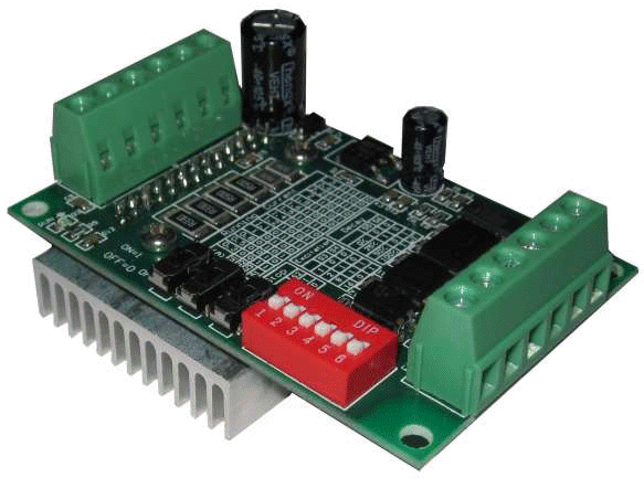
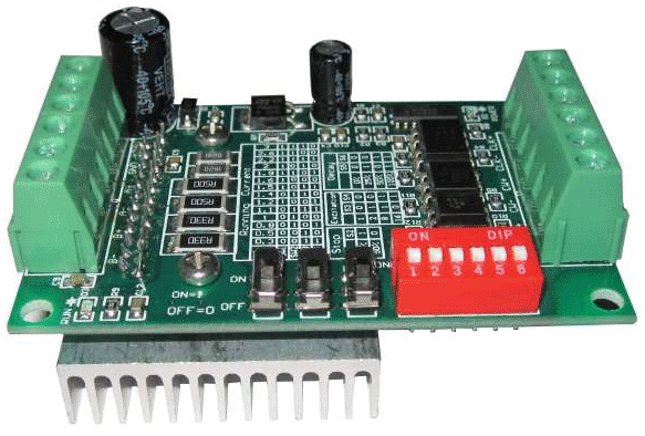
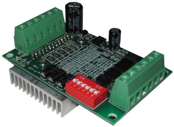
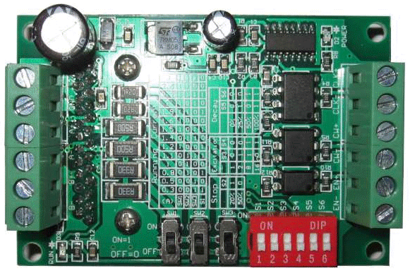
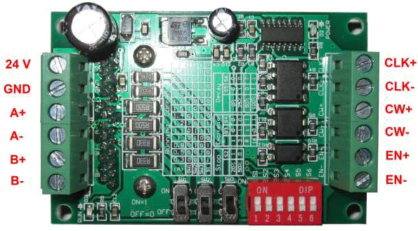
In the article, I talk in detail about an inexpensive popular module - the TB6560-V2 stepper motor driver. Based on my experience with it, I will focus on the practical application of this STEP/DIR driver.
General description.
The TB6560-V2 module is a bipolar stepper motor driver with STEP/DIR interface.
Made in the form of one board with dimensions 75 x 50 x 35 mm.
It is based on the specialized TOSHIBA TB6560 microcircuit. This link provides technical information about the chip.
Briefly about the main features of the module.
- Designed to control two-phase bipolar stepper motors.
- Has a galvanically isolated STEP/DIR interface.
- Provides stabilization of the phase currents of the motor at a given level.
- Maximum phase current up to 3 A, set discretely with DIP-switches on the board.
- Has the following engine control modes:
- full-step;
- half-step;
- microstepping 1/8 step;
- microstepping 1/16 step.
- In microstepping mode, it provides the shape of phase currents close to sinusoidal, which reduces noise and vibration. Provides 4 modes of winding current decay.
- Has built-in overheating protection.
- There is a current reduction mode to hold the rotor when the engine stops.
Technical characteristics of the module.
| Supply voltage | 10 ... 35 V , 24 V is recommended. |
| Phase current | 0.3 ... 3 A. Set with switches on the board. There are 14 adjustment steps in total. |
| Stepping modes |
The mode is set with switches on the board. |
| Interface | Opto-isolated STEP/DIR/ENABLE. |
| Maximum permissible current of the CW (DIR) and EN (ENABLE) signals | 50 mA |
| Maximum permissible current of the CLK (STEP) signal | 20 mA |
| The current of the CW (DIR), EN (ENABLE), CLK (STEP) signals at 5 V level at the input (limited by the resistors of the module) | 11 mA |
| Maximum frequency of the CLK signal (STEP) | 15 kHz |
| Minimum pulse width of the CLK signal (STEP) | 7.7 μs |
| Overheating protection | 170 °C |
| Operating temperature | - 10 … + 45 °C |
| Dimensions | 75 x 50 x 35 mm |
| Weight | 73 g |
STEP/DIR interface.
STEP/DIR is the main interface for stepper motor driver control. Consists of three signals:
- STEP;
- DIR;
- ENABLE.
STEP - step. This is a tactile signal. One impulse indicates that the rotor of the motor must be turned one step. The step is not the minimum discreteness of the stepper motor position, but the step of the driver. In micro stepping mode, this can only be part of the physical step of the motor.
As a rule, drivers respond to one of the edges of this signal.
The frequency of the STEP signal determines the speed of rotation of the engine. There are restrictions on the maximum STEP pulse repetition rate and minimum pulse width. This refers to the limitations of the driver. The rotation speed of a real motor has its own limitations associated with the parameters of the motor itself, winding current, mechanical loads, inertia, etc.
DIR - signal that determines the direction of rotation of the motor. It is assumed that at a high signal level, the motor rotates clockwise, at a low level - in the opposite direction.
ENABLE - signal for enabling the driver. The inhibiting signal level does not change the logic of the driver, but simply removes the voltage from the output. Used to stop the motor without holding current. A low signal level (no input voltage) allows the driver to work.
As a rule, for stepper motor drivers, the interface signals are galvanically isolated on optoelectronic devices. In power circuits with stepper motors, significant switching currents are present, which leads to a high level of noise and a shift in the voltage levels of the common wires (ground) of all modules in the system. Galvanic isolation is absolutely essential under these conditions.
External signals of the module.
The module is connected using two terminal blocks.
| Pin number | Signal |
Destination |
| 1 | CLK+ | STEP signal pins. The current is limited by a 330 ohm resistor. |
| 2 | CLK - | |
| 3 | CW+ | Direction of rotation signal (DIR) pins. The current is limited by a 330 ohm resistor. |
| 4 | CW- | |
| 5 | EN+ | Operation enable signal (ENABLE) pins. The current is limited by a 330 ohm resistor. |
| 6 | 0EN- |
| Pin number | Signal |
Destination |
| 1 | B- | Phase winding B |
| 2 | B+ | |
| 3 | A- | Phase winding A |
| 4 | A+ | |
| 5 | GND | Common wire |
| 6 | 24 V | Positive power signal |
Driver circuit TB6560-V2.
The driver circuit consists of:
- TB6560 chip, included according to the standard scheme;
- block for opto-isolation of input control signals:
- mode selection switches;
- unit for setting rated current (SW1-SW3);
- voltage stabilizer;
- block for determining the stop of the motor.
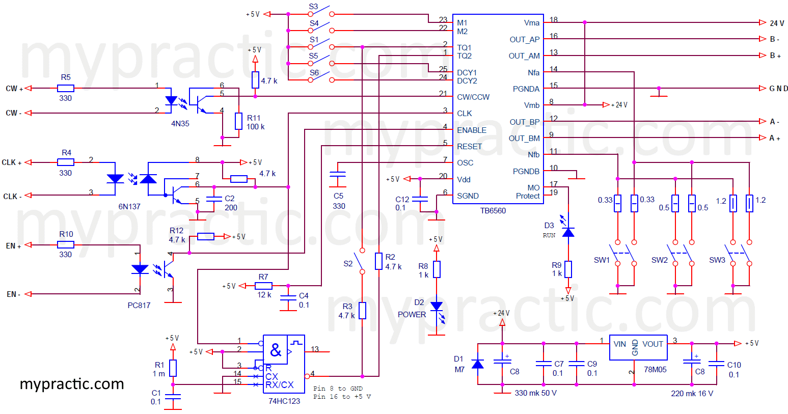
Schematic diagram of TB6560-V2 stepper motor driver.
Optoisolation of input signals is performed on optocouplers 4N35, 6N137 and PC817. A 6N137 fast optocoupler is used for the STEP signal. The frequency of the STEP signal can reach 15 kHz. The rest of the signals do not require such speed.
The unit for setting the rated current connects up to three resistors in parallel, thereby setting different resistances of the phase current sensors (NF resistors).
The only function of the TB6560-V2 that is not available on the TB6560 chip is to reduce the current when the motor is stopped. A very handy feature. When the motor stops, there is no need to keep the motor windings at full operating current. It is impossible to turn off the driver, since the rotor can turn from mechanical impact or be pulled to the nearest phase in micro stepping mode. Those. the current in the phases must be left, only reduced to the level of the holding current.
The motor stop detection unit is implemented on a 74HC123 one shot multi-vibrator (74HC23.pdf). The STEP signal restarts the one-shot on every negative edge. When the pulses of the STEP signal stop, i.e. the motor stops, the one-shot multi-vibrator finishes processing the last output pulse and goes into a high state (pin 4). The pulse time of the one-shot is set by the elements R1, C1 and is 45 ms. Thus, if the pulses of the STEP signal follow with a period of at least approximately 50 ms, then pin 4 of the 74HC123 chip is in a low state, and the operating current is determined by switch S1. When the STEP signal stops pulsing, pin 4 goes high and sets the TQ1 and TQ2 inputs of the TB6560 to undercurrent.
The lack of protective diodes in the driver circuit is surprising. If you rotate the engine in the off state of the driver, then it will work as a generator and the chip may fail. A simple diode limiter circuit is usually used to protect the driver's output switches. Two diodes must be connected to each of the four outputs of the TB6560: to ground and to the supply voltage (24 V signal). Given that the driver uses PWM output signals, the diodes must be high-frequency.
MOSFET transistors always contain protective diodes, but the developers of the TB6560 chip do not report anything about their parameters. If the motor will not run at high speed when the driver is off, no external protection diodes are needed.
Connection of control signals.
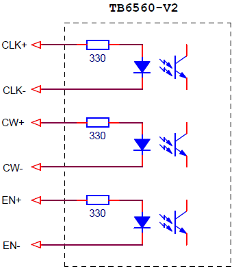
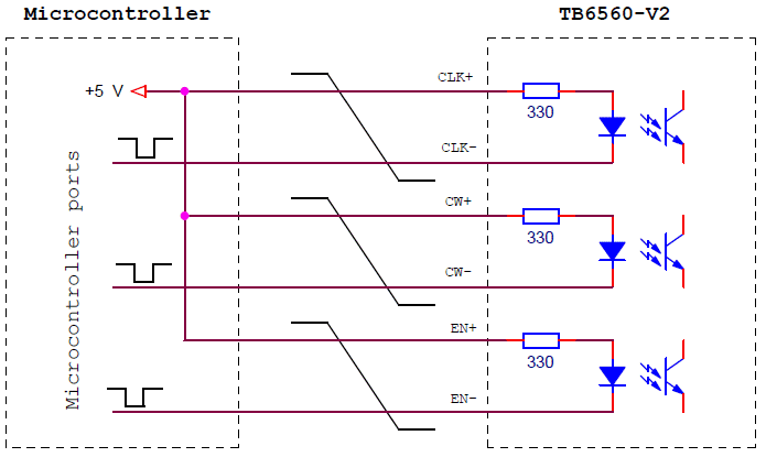
From a circuitry point of view, the input signals to the TB6560-V2 driver are optocoupler LEDs with current limiting resistors.
To transfer the signal to the active state, it is necessary to ensure the flow of current through the LED.
The easiest way is to apply 5V to the input. The current limiting resistors (330 ohms) are designed for this voltage. The current in this case will be approximately 11 mA. The current, which is fully provided by the outputs of modern microcontrollers.
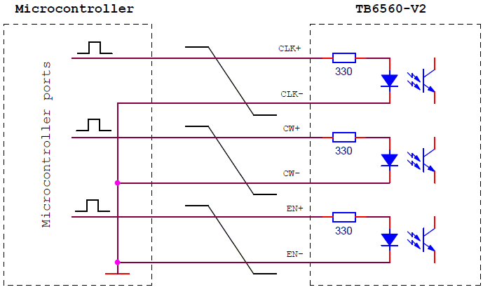
Wiring diagrams of the TB6560-V2 driver to microcontrollers can be as follows.
This is a circuit with high active levels at the outputs. If active low levels are required, the following scheme can be used.
In both circuits, each input is connected with two separate wires, although you can see that three wires are connected to the same point on the microcontroller board. For the first circuit, this is the ground, for the second + 5 V. You can connect three pins on the terminal block of the module and connect to the microcontroller with one wire.
This can only be done if the driver is placed in the immediate vicinity of the microcontroller. The system's immunity to interference will drop dramatically. When connecting each input with two wires, the interference to the communication wires will be subtracted from each other. Therefore, it is recommended to connect the driver to the microcontroller with separate twisted pairs for each signal.
Connecting a stepper motor to TB6560-V2 module.
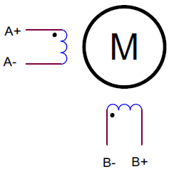
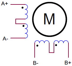
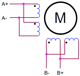
The TB6560-V2 driver controls only two phase bipolar stepper motors, so the motor must have two separate windings. Below are the diagrams for different types of motors.
4-lead motor.
An obvious option for connecting a classic bipolar motor.
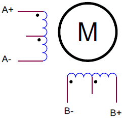
6 wire motor.
These are motors that can operate in unipolar and bipolar modes. The driver does not support unipolar mode. And in bipolar mode, such a motor can be connected in two ways:
Using all the windings.
Using half of the windings.
In the first case, the motor is used at full power, but requires twice the supply voltage than for the second circuit. In the second variant, the engine runs at reduced power.
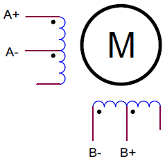
8-pin motor.
Such a motor can be connected according to the schemes of serial and parallel connection of the windings.
A circuit with windings connected in series requires twice the voltage, but half the current.
In contrast, a parallel winding circuit requires twice the current, but half the voltage.
In addition, in this circuit, the total inductance of the phase windings is 4 times less than in the previous one, which is important at high engine speeds.
Choice of module operation modes.
The operating modes of TB6560-V2 are set by switches located on the module board.
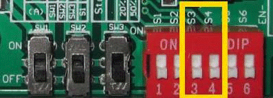
Stepper motor control mode.
Set by switches S3 and S4.
| Switches state | Mode | |
| S3 | S4 | |
| OFF | OFF | full-step |
| ON | OFF | half-step |
| ON | ON | microstepping 1/8 step |
| OFF | ON | microstepping 1/16 step |
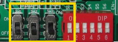
Setting the operating current (torque).
Set by switches SW1, SW2, SW3 and S1.
| Winding operating current, A | Switches state | |||
| SW1 | Sw2 | SW3 | S1 | |
| 0,3 | OFF | OFF | ON | ON |
| 0,5 | OFF | OFF | ON | OFF |
| 0,8 | OFF | ON | OFF | ON |
| 1 | OFF | ON | OFF | OFF |
| 1,1 | OFF | ON | ON | ON |
| 1,2 | ON | OFF | OFF | ON |
| 1,4 | OFF | ON | ON | OFF |
| 1,5 | ON | OFF | ON | ON |
| 1,6 | ON | OFF | OFF | OFF |
| 1,9 | ON | ON | OFF | ON |
| 2 | ON | OFF | ON | OFF |
| 2,2 | ON | ON | ON | ON |
| 2,6 | ON | ON | OFF | OFF |
| 3 | ON | ON | ON | OFF |
Setting the rotor holding current of a stopped motor.
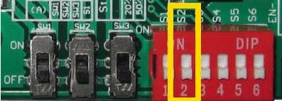
When the engine stops, the module automatically reduces the winding current to the value required to fix the rotor in a stable position. The value of this current can be selected with switch S2.
| Switch state S2 | Rotor holding current |
| ON | 20 % |
| OFF | 50 % |
Setting the current decay rate.
The mode is described in detail in the article on the TB6560 chip. In short, the mode determines the way of switching the output MOSFETs when switching off, and hence the rate of decrease in the current of the motor windings.
- When setting a slow current drop, the output signal shape in micro stepping mode becomes close to sinusoidal. This reduces noise, vibration, pulsation.
- However, a slow drop in current can lead to a violation of the proportions of the phase currents, which is important in micro stepping mode.
General recommendations for selecting the current decay rate:
- In micro stepping mode with high rotation speed (high switching frequency).
- Depends on motor parameters, is determined specifically for each type of engine and for operating conditions.
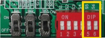
The current decay rate is set by switches S5, S6.
| Switches state | Сurrent decay rate | |
| S5 | S6 | |
| OFF | OFF | 0 % |
| ON | OFF | 25 % |
| OFF | ON | 50 % |
| ON | ON | 100 % |
The LEDs of the module.
The TB6560-V2 module contains two LEDs:
- The "POWER" LED is connected to the 5V circuit and indicates the presence of power.
- LED ”RUN” is connected to the MO output and lights up at the moments of the initial state of the diagram. Those. when the motor is rotating, it flashes with the frequency of the phase switching cycle.
Recommendations for use.
- TB6560-V2 drivers stabilize the output current. But they are designed to stabilize the current through an inductance in which the current cannot change instantly.
- In addition, the current stabilizer sensors are connected to ground, i.e. stabilizes the current flowing through the ground. This leads to the fact that any short circuit of the output to the ground or phase-to-phase short circuit (incorrect connection of the phase windings) disables the microcircuit.
- You can turn on the driver with an unconnected motor. There will be no trouble.
- As I wrote above in the comments to the TB6560-V2 circuit diagram, the driver does not contain output switches protection diodes. Therefore, it is prohibited to rotate the motor quickly when the driver is disconnected from the power supply. May lead to breakdown of output MOSFETs.
- When the upper MOSFET switches burn outt, a power supply voltage may be applied to the motor windings. The current will not be limited by anything and the stepper motor will burn out. To avoid this situation, I would recommend using a fuse in the driver supply circuit. The motor winding will not burn out instantly. The fuse will have time to blow.
This article describes how to control the TB6560 driver using Arduino.
Probably TB6560-V2 is not the most versatile and multifunctional stepper motor driver. But at the time of this writing, it cost $ 6-9. And this is not for a chip, but for a full-fledged module with opto-isolated inputs, a radiator, not a small current up to 3 A. My experience of operating it shows that failures are usually associated with installation errors or violations of operating requirements.

