In the lesson, we will learn about pulse width modulation, the implementation of this control method in Arduino controllers, and the modes and functions of working with PWM in Arduino.
Previous lesson List of lessons Next lesson
Let's break for a lesson from developing a refrigerator controller in order to learn how to work with the Arduino pulse-width modulator.
In our development, it is this method of power control on the Peltier module that is used.
Pulse width modulation.
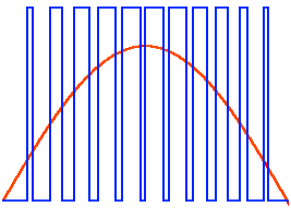
Pulse Width Modulation (PWM) is a way to control the power on the load by changing the duty cycle of the pulses at a constant amplitude and pulse frequency.
There are two main areas of application of pulse-width modulation:
- In secondary power sources, various power regulators, brightness regulators of light sources, speed of rotation of collector motors, etc. In these cases, the use of PWM can significantly increase the efficiency of the system and simplify its implementation.
- To form an analog signal using the digital output of the microcontroller. A kind of digital-to-analog converter (DAC). Very easy to implement, requires a minimum of external components. Often one RC circuit is enough.
The principle of regulation using PWM is to change the width of the pulses at a constant amplitude and frequency of the signal.
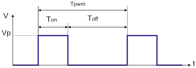
In the diagram you can see the main parameters of the PWM signal:
- Vp - pulse amplitude;
- Ton – active (on) signal state time;
- Toff – signal off state time;
- Tpwm - PWM period time.
It is even intuitively clear that the power at the load is proportional to the ratio of the time the signal is on and off.
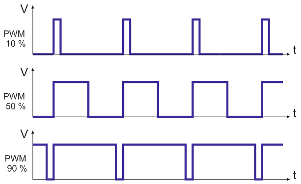
This ratio determines the duty cycle of the PWM:
Kw = Ton / Tpwm.
It shows how much of the period the signal is on. May change:
- from 0 – the signal is always off;
- up to 1 - the signal is on all the time.
The most commonly used percentage fill factor. In this case, it is in the range from 0 to 100%.
The average value of the electrical power at the load is strictly proportional to the duty cycle. When they say that the PWM is, for example, 20%, they mean exactly the duty cycle.
Formation of an analog signal.
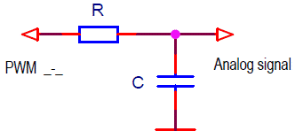
If the PWM signal is passed through a low-pass filter, then at the filter output we will get an analog signal, the voltage of which is proportional to the duty cycle of the PWM.
V = Kw * Vp
As a low-pass filter, you can use the simplest RC circuit.
Due to the non-ideal characteristic of such a filter, the cutoff frequency must be at least an order of magnitude smaller than the PWM frequency. For a simple RC filter, the cutoff frequency is calculated using the formula:
F = 1 / (2 π R C).
- When the cutoff frequency of the low-pass filter increases, pulsations with the PWM frequency increase at the filter output.
- Decreasing the filter's cutoff frequency reduces the response time of the analog output signal to changes in pulse width.
From this follows the main disadvantage of pulse-width modulation. The method is capable of synthesizing only rather slow analog signals or requires the use of low-pass filters with a high quality factor, which are difficult to implement.
I would recommend:
- In the case when there are no strict requirements for the speed of the analog signal, choose a deliberately low filter cutoff frequency.
- If it is necessary to optimize the performance of an analog converter, it is better to simulate the circuit.
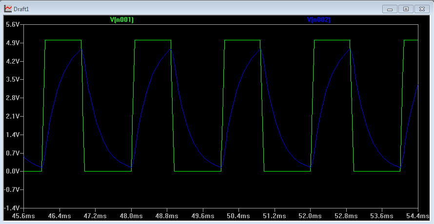
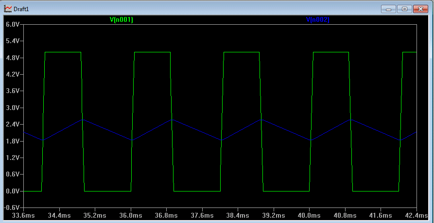
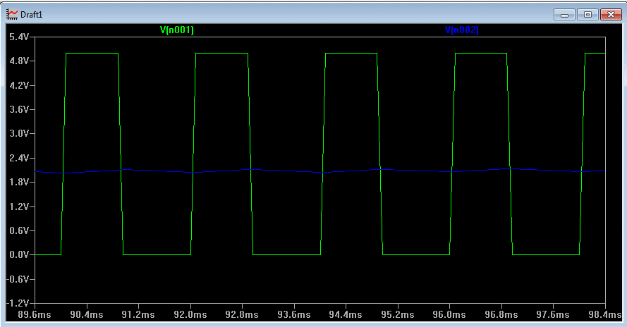
Even the simplest simulation programs calculate the ripple level quite accurately. Here are the SwCAD simulation results for 500Hz PWM and RC filters with cutoff frequencies of 500Hz, 50Hz and 5Hz. The green color shows the PWM diagram, the blue color shows the voltage at the output of the RC filter.
Cutoff frequency 500 Hz (10 kΩ, 32 nF).
Cutoff frequency 50 Hz (10 kΩ, 320 nF).
Cutoff frequency 5 Hz (10 kΩ, 3.2 µF).
The conversion accuracy of pulse-width modulators is determined by the error in the amplitude of the pulses (i.e., the stability of the microcontroller power supply) and the value of the voltage drop across the digital output switches of the microcontroller. As a rule, the accuracy of PWM microcontrollers is not high. To achieve high accuracy of PWM conversion, you can use an additional circuit with analog switches and a reference voltage source.
The disadvantages of using pulse-width modulators as a DAC also include a high output impedance. It is determined by the resistance of the RC filter resistor and cannot be low due to the low load capacity of the microcontroller outputs.
Pulse width modulators in Arduino.
Arduino boards based on ATmega168/328 microcontrollers have 6 hardware pulse-width modulators. PWM signals can be generated on pins 3, 5, 6, 9, 10, 11.
Hardware PWM is controlled using the analogWrite() system function.
void analogWrite(pin, val)
The function puts the pin in PWM mode and sets the duty cycle for it. It is not necessary to call the pinMode() function before using analogWrite() to set the pin to output mode.
Arguments:
- pin – pin number for PWM signal generation.
- val – PWM duty cycle. Without further settings, val ranges from 0 to 255 and corresponds to a duty cycle of 0 to 100%. Those, the bit depth of system PWM in Arduino is 8 bits.
analogWrite(9, 25); // on pin 9 PWM = 10%
Arduino PWM frequency 488.28 Hz.
All three Arduino timers are used to generate PWM.
| Timer | Used to generate PWM on pins |
| Timer 0 | pins 5 и 6 |
| Timer 1 | pins 9 и 10 |
| Timer 2 | pins 3 и 11 |
If the timer is used for other purposes, such as an interrupt, then the PWM parameters of the corresponding pins may not correspond to those indicated above.
Therefore, when using the MsTimer2, TimerOne or similar libraries, some pins cannot be used as PWM signals.
Increasing the frequency and bit depth of PWM Arduino.
The Arduino system sets the following parameters on all PWM pins:
- frequency 976.56 Hz for Timer 0;
- frequency 488.28 Hz for Timer 1 and Timer 2;
- Resolution 8 bits (0…255).
Very low frequency. For most applications, it is completely unacceptable.
In the development of the Peltier module controller, started in the previous lesson, the PWM frequency must be at least 30-50 kHz. There are a lot of proposals on the Internet for increasing the PWM frequency. All of them describe methods for increasing the frequency to 31 kHz. In principle, an acceptable option, but I wanted more.
I figured out the Timer 1 of the ATmega168 / 328 microcontroller, switched the PWM to high-speed mode and achieved the Arduino PWM frequency to 62.5 kHz. At the same time, I learned how to change the PWM bit depth. In order not to delve into the documentation for ATmega168/328 microcontrollers next time, I have summarized all possible PWM options for timer 1 in a table.
The lines from the right column for the selected option must be written in the setup() function.
Options for PWM parameters on pins 9 and 10 of Arduino (timer 1).
| PWM bit depth | PWM frequency | Mode setting commands |
| 8 bits | 62 500 Hz | TCCR1A = TCCR1A & 0xe0 | 1; TCCR1B = TCCR1B & 0xe0 | 0x09; |
| 7 812,5 Hz | TCCR1A = TCCR1A & 0xe0 | 1; TCCR1B = TCCR1B & 0xe0 | 0x0a; |
|
| 976,56 Hz | TCCR1A = TCCR1A & 0xe0 | 1; TCCR1B = TCCR1B & 0xe0 | 0x0b; |
|
| 244,14 Hz | TCCR1A = TCCR1A & 0xe0 | 1; TCCR1B = TCCR1B & 0xe0 | 0x0c; |
|
| 61,04 Hz | TCCR1A = TCCR1A & 0xe0 | 1; TCCR1B = TCCR1B & 0xe0 | 0x0d; |
|
| 9 bits | 31 250 Hz | TCCR1A = TCCR1A & 0xe0 | 2; TCCR1B = TCCR1B & 0xe0 | 0x09; |
| 3 906,25 Hz | TCCR1A = TCCR1A & 0xe0 | 2; TCCR1B = TCCR1B & 0xe0 | 0x0a; |
|
| 488,28 Hz | TCCR1A = TCCR1A & 0xe0 | 2; TCCR1B = TCCR1B & 0xe0 | 0x0b; |
|
| 122,07 Hz | TCCR1A = TCCR1A & 0xe0 | 2; TCCR1B = TCCR1B & 0xe0 | 0x0c; |
|
| 30,52 Hz | TCCR1A = TCCR1A & 0xe0 | 2; TCCR1B = TCCR1B & 0xe0 | 0x0d; |
|
| 10 bits | 1 5625 Hz | TCCR1A = TCCR1A & 0xe0 | 3; TCCR1B = TCCR1B & 0xe0 | 0x09; |
| 1 953,13 Hz | TCCR1A = TCCR1A & 0xe0 | 3; TCCR1B = TCCR1B & 0xe0 | 0x0a; |
|
| 244,14 Hz | TCCR1A = TCCR1A & 0xe0 | 3; TCCR1B = TCCR1B & 0xe0 | 0x0b; |
|
| 61,04 Hz | TCCR1A = TCCR1A & 0xe0 | 3; TCCR1B = TCCR1B & 0xe0 | 0x0c; |
|
| 15,26 Hz | TCCR1A = TCCR1A & 0xe0 | 3; TCCR1B = TCCR1B & 0xe0 | 0x0d; |
The following sketch generates 62.5kHz PWM at pin 9 with a duty cycle of approximately 10%.
void setup() {
// PWM 8 bits, 62.5 kHz
TCCR1A = TCCR1A & 0xe0 | 1;
TCCR1B = TCCR1B & 0xe0 | 0x09;
analogWrite(9, 25); // at pin 9 PWM=10%
}
void loop() {
}
This is the maximum possible Arduino PWM frequency for most boards (with a oscillator frequency of 16 MHz).
In the next lesson, we will return to the development of the Peltier module controller.
Previous lesson List of lessons Next lesson

