In this article, I talk about STEP/DIR stepper motor drivers, the advantages of using them, and the STEP/DIR control interface.
Previous lesson List of lessons Next lesson
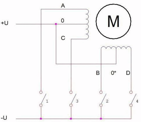
In previous lessons, to connect stepper motors to the Arduino board, we used simple drivers-switches, which, according to signals from the microcontroller, switched the motor windings. All the logic of the operation was implemented in the microcontroller program.
The advantage of this solution is obvious - simplicity and minimum of hardware. Just four transistor switches for unipolar stepper motors or the L298N chip for bipolar ones are enough to control them. And the phase switching program is not complicated, it does not take up a lot of microcontroller resources. Another way for controlling stepper motors is to use STEP/DIR drivers.
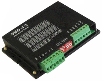
STEP/DIR driver is a hardware stepper motor control module that uses the STEP/DIR protocol to communicate with the microcontroller.
In addition, STEP/DIR drivers provide a wide range of additional functionality:
- stabilization of phase currents;
- micro step mode;
- protection of output swithes from load short circuit;
- complex switching to accelerate the current drop in the windings;
- overheating protection;
- opto-isolation of control signals.
Current stabilization of the phase windings.
The main disadvantage of simple stepper motor drivers is the lack of stabilization of the winding current.
In previous lessons, I have already touched on this topic.
We connected the windings to the power source in the simplest way - through transistor switches.
What are the disadvantages of this scheme?
The direct current through the winding when the switch is closed is determined by the Ohm's law:
Iphase = (Usupply - Uswitch) / Rwinding
The phase current is defined as the ratio of the supply voltage to the active resistance of the winding. You cannot connect any motor at random. It is necessary to select the stepper motor according to the resistance of the windings or change the supply voltage.
In the previous lesson, I used a motor with a winding resistance of 1.65 ohms. If I connected it to a 12 V power supply, the current would be over 7 A. The motor would just burn out. To provide the required phase current of 1 A, the voltage of the power supply must be 1.65 Ohm * 1 A = 1.65 V. I do not know where to get such a power supply. In addition, a voltage drops on the closed swithes comparable to the voltage on the winding, which must also be taken into account in the calculations. And it is not stable and not strictly defined. No acceptable options are visible at this power supply voltage.
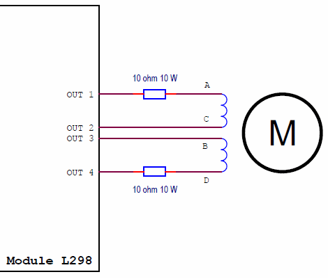
To connect such a motor, I used limiting resistors in series with the windings.
The formula for calculating the phase current looks like this:
Iphase = (Usupply - Uswitches) / (Rwinding + Rlimit)
But with such a scheme, significant power can be released on the limiting resistors, often exceeding the power consumed by the motor. On low-power engines, this option is more or less acceptable. As the motor power increases, it becomes questionable. In the circuit from the previous lesson, each limiting resistor dissipated power up to 7.4 watts.
Iphase =( 12 V-2 V ) / (1.65 + 10) = 0.86 A
P = I2 * R = 0,86 * 0,86 * 10 = 7.4 W
And this is for a phase current of 0.86 A and only on one resistor. Even on this engine, practically unacceptable losses.
Simple drivers can be used with a limited number of motor types, or with low-power engines.
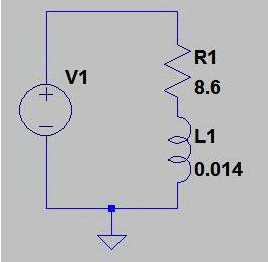
The second disadvantage of simple switches-drivers is associated with the rate of current rise in the motor windings. In lessons 28 and 29, I connected the FL57STH76-1006 unipolar motor through transistor switches to a 12V power source. The motor winding resistance is 8.6 Ohm, the inductance is 14 mH.
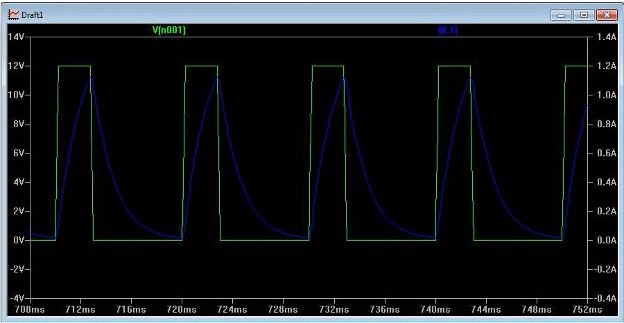
Let's see what form the phase current will have for a rotation speed of 1 revolution per second. This speed corresponds to a phase switching period of 1 sec / 400 steps per revolution = 2.5 ms.
I simulated the circuit in the SwCAD package.
The diagram shows how the current rise through the winding (blue) is delayed in relation to the voltage across the winding (green). In the previous lesson, I calculated that for this motor, even with zero resistance of the windings, the phase current will reach 1 A in a time:
T = I * L / U = 1 A * 14 mH / 12 V = 1.2 ms.
And all these calculations are for a rotation speed of 1 revolution per second. In practice, I got a maximum speed of 1 revolution per second. Then the motor goes out of synchronicity. Not enough torque.
The way out of the situation is to stabilize the phase current. A current stabilizer is a circuit that changes the voltage on the load, trying to provide a given current. I.e., the voltage on the load depends on its resistance. If the resistance increases, the current stabilizer increases the voltage in order to provide a given current. As the load resistance decreases, the voltage decreases. Naturally, the current stabilizer operates in a limited voltage range. If it is impossible to provide the required current, it forms the maximum possible voltage across the load.
For example, if the current stabilizer is powered from a 12 V source, it is necessary to stabilize the current of 1 A, and the load resistance of 1000 ohms is connected, then the voltage on the load will be 12 V. Although theoretically the current stabilizer should provide a voltage of 1000 V.
For stepper motors, this is the ideal law for controlling the winding currents.
- You can connect a motor with any winding resistance. The current will be limited automatically.
- The maximum possible rate of current rise in the windings is provided. At the beginning of the phase pulse, the current stabilizer will output the maximum voltage on the winding, and as the current increases, it will decrease to the required value.
Of course, we are talking about switching regulators with high efficiency. The power section of the current stabilizers in the motor windings practically consists of switches only. The role of the smoothing filter is performed by the inductance of the winding.
It is quite problematic to implement current stabilization on the control microcontroller. For example, at a speed of 10 revolutions per second, and the number of motor steps per full revolution equal to 400, the duration of the phase switching pulse is 250 μs. During this time, the PWM regulator implemented in the microcontroller program will not have time to perform the current stabilization functions. Approximately every 10 μs, it is necessary to measure the phase current and calculate the new value of the PWM. But it is necessary to implement two separate regulators for different windings. And the rotation speeds can be higher.
Therefore, the current stabilization function is usually implemented on a separate hardware driver. Even in this case, as a rule, not a PWM regulator is used, but a synchronous relay regulator. The relay regulator closes the switches and monitors the current using an analog comparator. When the set value of the current is reached, the switches open. When the current drops below the threshold, they close again. Thus, a current with a given value is created in the winding. The ripple is smoothed out by the winding inductance. The relay regulator is simple to implement and, in contrast to the PWM regulator, has a high speed of response.
In addition, stabilization of the phase current is necessary when implementing a micro-stepping motor control mode. To install the rotor in a certain position between the phase poles of the motor, it is necessary to provide a given proportion of the winding currents. In the article about the TB6560 driver, you can see the diagrams of the phase currents for the micro stepping mode with 16 gradations. The current stabilization accuracy must be high enough.
STEP / DIR interface.
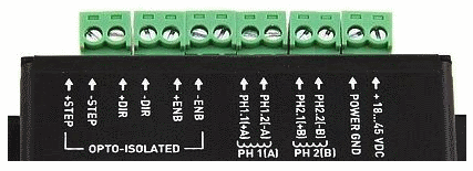
De facto, this is the main interface for controlling stepper motor hardware drivers. Three signals are used to communicate with the microcontroller.
- STEP
- DIR
- ENABLE
STEP - Each impulse initiates one step rotation of the motor. If the driver operates in half stepping or micro-stepping modes, then the rotation takes place not by the physical step of the motor, but by a part of the step determined by the mode. For a half stepping mode, this is half a physical step, for a micro stepping mode, it is a micro step. STEP/DIR drivers react to the front of the control pulse, usually a negative edge.
The pulse frequency of the STEP signal determines the speed of rotation of the motor. There are, of course, limitations on the maximum pulse rate of the STEP signal and on the minimum pulse width. The driver must have time to receive, select and process each pulse. A real motor will add its own speed limits related to mechanical parameters, winding currents, number of poles, mechanical loads, etc.
DIR is a signal that sets the direction of rotation of the motor. Typically, when the signal is high, the motor will rotate clockwise. The DIR signal must be generated before the STEP pulse.
ENABLE - signal for enabling the driver. The inhibiting signal level removes the voltage at the driver output. The logic of the device does not change. The signal is used to stop the motor in no holding current mode. The rotor position is not fixed. The permissive level of the ENABLE signal is low, i.e. no voltage. If the signal is not used, then you can simply not connect it, leave the driver input ”in the air".
As a rule, all STEP / DIR driver signals are galvanically isolated using optoelectronic components. Switching of the motor windings causes significant pulse interference in the power supply circuits and leads to a shift in the voltage levels of the common (ground) wires of all electronic modules of the system. Under these conditions, galvanic isolation of the control signals is absolutely necessary.
Advantages of using STEP/DIR drivers.
I will summarize the positive qualities of STEP / DIR drivers.
- Stabilization of the phase current and as a result:
- Motors with any winding resistance can be connected.
- High rate of rise of current in the windings, which allows to increase the speed of rotation.
- Micro stepping control mode. Allows the implementation of systems with high positioning accuracy using motors with a limited number of physical steps. In the next lesson, I'll turn my 400 steps per revolution motor into a 6400 steps full revolution motor.
- Protection of output switches from load short circuit;
- Optimal switching of output switches to accelerate the drop in currents in the windings. Allows you to increase the rotation speed and reduce vibration.
- Overheat protection.
- Opoisolation of control signals. Provides high noise immunity of the system.
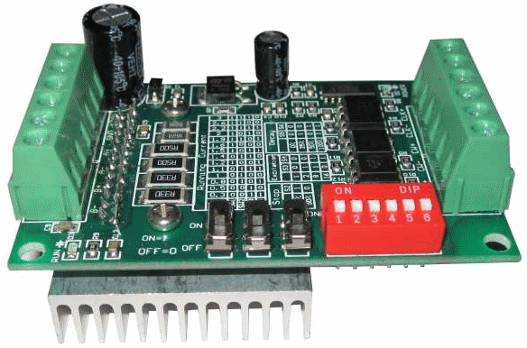
As an example of a STEP / DIR driver, I can give the TB6560-V2 module.
This is one of the most inexpensive STEP / DIR drivers. However, it provides all the functions and modes listed in the article.
In the next lesson, we will connect this driver to the Arduino board. I will introduce the STEP / DIR driver control library.

Very interesting article, the content is very detailed, thank you for sharing
HI.
THANKS FOR YOUR GOOD AND CLEAR LESSONS. WE ARE EAGER TO SEE YOUR NEXT LESSONS
BEST REGARDS
NADER AHMADI
Thanks for the nice words.
I will continue.