In the lesson we will learn how to connect a DS18B20 temperature sensor to the Arduino board, how to control it using the OneWire library. We will develop an accurate thermometer.
Previous lesson List of lessons Next lesson
The DS18B20 is an integral temperature sensor with a 1-Wire digital serial interface. The sensor has unique parameters and functionality. You can read more about it at the link.
Now I will emphasize the features of this device, thanks to which it became so widespread. The sensor has the following properties:
- High accuracy of measurement, the error does not exceed 0.5 ° C. The sensor is calibrated during manufacture, does not require additional calibration.
- Resolution is set by software and reaches 0.0625 ° C for a maximum resolution of 12 bits.
- Wide range of temperature measurement -55 ... + 125 ° C.
- The sensor converts the temperature into a digital code, i.e. no additional ADC is required.
- Information is transmitted via a 1-Wire serial protocol; only three wires are required to connect the temperature sensor to the microcontroller.
- Supports “parasitic power” mode in which the sensor receives power from the communication line. In this mode, to connect the device to the microcontroller, two wire lines are enough.
- Multiple sensors can be connected to the same communication line.
This is the main thing. The various modes and functionality associated with the operation of several devices on a single line, with an alarm signal, and others in this article, I do not consider. The publication focuses on the practical use of the sensor in the most common mode.
Connecting the DS18B20 sensor to the microcontroller.
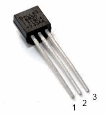
The most common version of the DS18B20 in the TO-92 package.
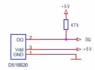
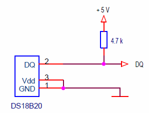
The pins on the wiring diagrams are indicated for this option. There are two standard schemes for connecting the DS18B20 to a microcontroller.
Power supply circuit with external source.
It's simple: ground, power, data signal. The pull-up resistor is strictly necessary and is installed near the microcontroller pin.
The circuit in the “parasitic power” mode allows you to connect the thermal sensor to the microcontroller with just two wires, which is especially important when placing the sensor at a considerable distance from the controller.
In this mode, the data bus signal charges the internal capacitor of the sensor and due to the energy on it, the device is powered at a low bus level. The “parasitic power” mode has many features. You can read the link. Now I say the main thing that in this mode, the sensor does not guarantee operation at temperatures above 100 ° C. It is necessary to use a circuit with external power.
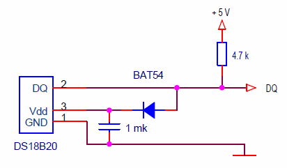
For this case, I use the following scheme.
The sensor operates in the mode of external power supply, which is stored through a diode on an additional capacitor. In my devices, the scheme works without problems, but I'm not sure that the OneWire library supports this option. I used this scheme only on PIC controllers with my own library.
Information exchange with the thermal sensor via the 1-Wire interface bus.
I will list only the operations we need to work with the device:
- Initialization – the sequence of pulses that start any operation on the bus.
- Byte recording - transfers a data byte to the DS18B20 device.
- Byte reading - receive data from the DS18B20 device.
These three operations are enough to work with the thermal sensor, they are all supported by the OneWire library.
Arduino OneWire library for working with the 1-Wire interface.
You can download the latest version of the OneWire library at this link. How to install it can be viewed in lesson 9.
We are interested in the following methods.
OneWire (uint8_t pin);
Constructor, Pin - the number of the pin to which the sensor is connected.
OneWire sensDs (14); // sensor connected to pin 14
uint8_t reset (void);
Initialization of the bus operation. Any data exchange operation should begin with this command. Returns:
- 1 - if the device is connected to the bus (there was a response impulse of presence);
- 0 - if the device is not on the bus (there was no response pulse).
void write (uint8_t v, uint8_t power = 0);
Write byte. Sends a byte to the device on the bus.
- v - byte;
- power - a sign of the choice of power mode;
- power = 0 - power supply from an external source
- power = 1 - “parasitic” power supply.
uint8_t read (void);
Byte reading - receives a byte transmitted by the device. Returns the value of the received byte.
These commands are enough to work with the DS18B20 sensor. You can add methods for writing and reading blocks of bytes and a function for calculating the checksum.
void write_bytes (const uint8_t * buf, uint16_t count, bool power = 0);
Writing a block of bytes.
- buf - pointer to the array;
- count - number of bytes;
- power - sign of the choice of power mode.
void read_bytes (uint8_t * buf, uint16_t count);
Reading a block of bytes.
- buf - pointer to the array;
- count - number of bytes.
static uint8_t crc8 (const uint8_t * addr, uint8_t len);
The function of calculating the 8-bit checksum.
- addr - pointer to the data array;
- len is the number of bytes.
Returns the calculated code.
The sequence of operations with DS18B20.
I will give and explain the simplest sequence of commands. To measure the temperature, you must perform the following steps:
- sensDs.reset () - Initialization. Performs the bus reset, preparing it for a new operation.
- sensDs.write (0xCC, power) - Skip ROM command. We have only one sensor on the bus. Therefore, there is no need to search for a device with the correct address. We miss this operation.
- sensDs.write (0x44, power) - The command initiates temperature measurement.
- Pause 1 sec. Waiting for the time required for the sensor to convert temperature. This time depends on the selected sensor resolution. We use a maximum resolution of 12 bits. This permission is set in the sensor by default. The conversion time for it is 750 ms. If another resolution is needed, then it must be specified with additional commands.
- sensDs. reset () - Initialization. We are going to perform a new operation on the 1-Wire bus.
- sensDs.write (0xCC, power) - Skip ROM command.
- sensDs.write (0xBE, power) - The command for reading the sensor memory. The command is used to read all 9 bytes of DS18B20 memory.
| Byte 0 | Temperature, low byte |
| Byte 1 | Temperature, high byte |
| Byte 2 | Th Alarm threshold register |
| Byte 3 | Tl Alarm threshold register |
| Byte 4 | Configuration Register |
| Byte 5 | Reserved |
| Byte 6 | Reserved |
| Byte 7 | Reserved |
| Byte 8 | CRC Cyclic Code |
- read_bytes (buf, 9) - Reading 9 data bytes.
- crc8 (addr, 8) - Calculation of the control code of the data.
- Comparison of the control code with the accepted one.
After this sequence of operations, the temperature value is contained in the first two bytes of the 9-byte array.
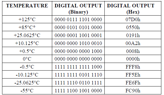
Negative temperature is transmitted in an additional code.
The low digit has a weight of 0.0625 ° C.
Arduino thermometer project using a DS18B20 sensor.
We will create a thermometer with functions similar to devices from Lesson 24 and Lesson 25. Using the DS18B20 thermal sensor allows you to achieve:
- high measurement accuracy of 0.5 ° C;
- high resolution 0.0625 ° C:
- measuring range is -55 ... +125 ° C.
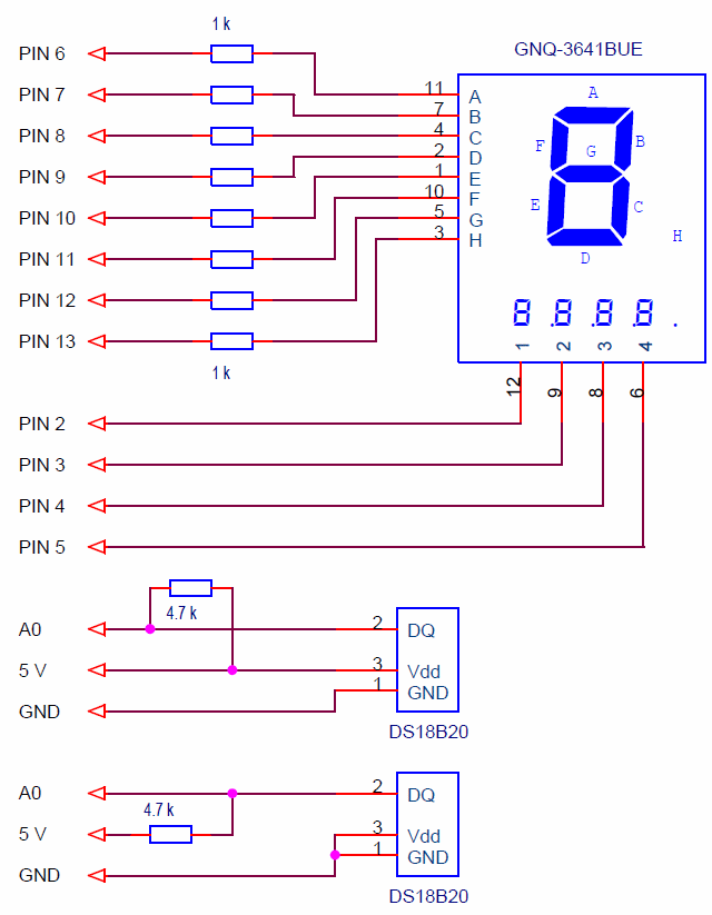
Schematic diagram of a thermometer with a sensor DS18B20.
The Led display is connected in the usual way from the previous lessons. There are two options for connecting the thermal sensor: with external power supply and “parasitic power supply.”
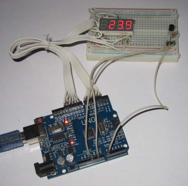
On my layout, the device looks like this.
Resident program of the Arduino-thermometer.
The structure and most of the program from previous lessons 24 and 25. The sequence of operations for the DS18B20 is described in detail above. Therefore, I will immediately give a sketch of the program.
// thermometer, sensor DS18B20
#include <MsTimer2.h>
#include <Led4Digits.h>
#include <OneWire.h>
#define POWER_MODE 0 // power mode, 0 - external, 1 - parasitic
// display type 1; digit pins 5,4,3,2; segment pins 6,7,8,9,10,11,12,13
Led4Digits disp(1, 5,4,3,2, 6,7,8,9,10,11,12,13);
OneWire sensDs (14); // the sensor is connected to pin 14
byte bufData[9]; // data buffer
float temperature; // measured temperature
void setup() {
MsTimer2::set(2, timerInterrupt); // set the interrupt period by timer 2 ms
MsTimer2::start(); // enable timer interrupt
Serial.begin(9600); // initialize the port, speed 9600
}
void loop() {
sensDs.reset(); // bus reset
sensDs.write(0xCC, POWER_MODE); // skip ROM
sensDs.write(0x44, POWER_MODE); // measure initialization
delay(900); // пауза 0,9 сек
sensDs.reset(); // bus reset
sensDs.write(0xCC, POWER_MODE); // skip ROM
sensDs.write(0xBE, POWER_MODE); // sensor read command
sensDs.read_bytes(bufData, 9); // read sensor memory, 9 bytes
if ( OneWire::crc8(bufData, 8) == bufData[8] ) { // CRC check
// the data is correct
temperature= ((float)((int)((unsigned int)bufData[0] | (((unsigned int)bufData[1]) << 8)))) * 0.0625 + 0.03125;
// output of the measured temperature to the display
if (temperature >= 0) {
// temperature is positive
disp.print((int)(temperature * 10.), 4, 1);
}
else {
// temperature is negative
disp.print((int)(temperature * -1 * 10.), 3, 1);
disp.digit[3]= 0x40; // shows minus
}
disp.digit[1] |= 0x80; // lit the point of the second digit
// transmission of the temperature to the computer
Serial.println(temperature);
}
else {
// CRC error, display ----
disp.digit[0]= 0x40;
disp.digit[1]= 0x40;
disp.digit[2]= 0x40;
disp.digit[3]= 0x40;
}
}
//-------------------------------------- interrupt handler 2 ms
void timerInterrupt() {
disp.regen(); // regeneration of the display
}
You can download the sketch here.
The program uses OneWire, MsTimer2 and Led4Digits libraries.
Do not forget to select the sensor power supply mode in the program:
#define POWER_MODE 0 // power mode, 0 - external, 1 - parasitic
The high-level program for the Arduino thermometer-recorder.
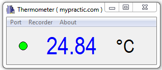
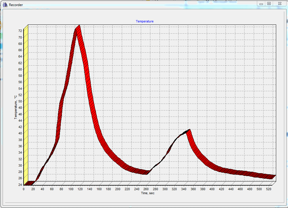
The Thermometer program from lesson 24 works with this device. In the lesson you can download the program, get information on the installation and its application.
Realization of temperature measurement by a parallel process.
In the thermometer project, the DS18B20 thermal sensor is controlled in the main program loop. The delay of 0.9 seconds is implemented by the function delay (). The program at this time hangs and no other action can not produce. It’s good that we don’t have to do anything else in the thermometer. And if we have a complex program with many other tasks.
Therefore, I want to show a version of the program in which the exchange of information with the sensor occurs in a parallel process in the interrupt handler. Functionally, this version of the program is similar to the previous one, but allows you to perform the necessary actions in the main loop without significant delay.
// thermometer, sensor DS18B20
#include <MsTimer2.h>
#include <Led4Digits.h>
#include <OneWire.h>
#define POWER_MODE 0 // power mode, 0 - external, 1 - parasitic
#define MEASURE_PERIOD 500 // measurement time * 2 ms
// display type 1; digit pins 5,4,3,2; segment pins 6,7,8,9,10,11,12,13
Led4Digits disp(1, 5,4,3,2, 6,7,8,9,10,11,12,13);
OneWire sensDs (14); // the sensor is connected to pin 14
int timeCount; // measurement time counter
boolean flagSensReady; // sign of data readiness from the sensor
byte bufData[9]; // data buffer
float temperature; // measured temperature
void setup() {
MsTimer2::set(2, timerInterrupt); // set the interrupt period by timer 2 ms
MsTimer2::start(); // enable timer interrupt
Serial.begin(9600); // initialize the port, speed 9600
}
void loop() {
if ( flagSensReady == true ) {
flagSensReady= false;
// data ready
if ( OneWire::crc8(bufData, 8) == bufData[8] ) { // CRC check
// the data is correct
temperature= ((float)((int)((unsigned int)bufData[0] | (((unsigned int)bufData[1]) << 8)))) * 0.0625 + 0.03125;
// output of the measured temperature to the display
if (temperature >= 0) {
// temperature is positive
disp.print((int)(temperature * 10.), 4, 1);
}
else {
// temperature is negative
disp.print((int)(temperature * -1 * 10.), 3, 1);
disp.digit[3]= 0x40; // shows minus
}
disp.digit[1] |= 0x80; // lit the point of the second digit
// transmission of the temperature to the computer
Serial.println(temperature);
}
else {
// CRC error, display ----
disp.digit[0]= 0x40;
disp.digit[1]= 0x40;
disp.digit[2]= 0x40;
disp.digit[3]= 0x40;
}
}
}
//-------------------------------------- interrupt handler 2 ms
void timerInterrupt() {
disp.regen(); // regeneration of the display
// DS18B20 Parallel Process Control
timeCount++; if ( timeCount >= MEASURE_PERIOD ) { timeCount=0; flagSensReady=true; }
if (timeCount == 0) sensDs.reset(); // bus reset
if (timeCount == 1) sensDs.write(0xCC, POWER_MODE); // skip ROM
if (timeCount == 2) sensDs.write(0x44, POWER_MODE); // measure initialization
if (timeCount == 480) sensDs.reset(); // bus reset
if (timeCount == 481) sensDs.write(0xCC, POWER_MODE); // skip ROM
if (timeCount == 482) sensDs.write(0xBE, POWER_MODE); // read sensor memory, 9 bytes
if (timeCount == 483 ) bufData[0]= sensDs.read(); // read sensor memory
if (timeCount == 484 ) bufData[1]= sensDs.read(); // read sensor memory
if (timeCount == 485 ) bufData[2]= sensDs.read(); // read sensor memory
if (timeCount == 486 ) bufData[3]= sensDs.read(); // read sensor memory
if (timeCount == 487 ) bufData[4]= sensDs.read(); // read sensor memory
if (timeCount == 488 ) bufData[5]= sensDs.read(); // read sensor memory
if (timeCount == 489 ) bufData[6]= sensDs.read(); // read sensor memory
if (timeCount == 490 ) bufData[7]= sensDs.read(); // read sensor memory
if (timeCount == 491 ) bufData[8]= sensDs.read(); // read sensor memory
}
You can download the sketch here.
After receiving data from the DS18B20 sensor, a sign of data readiness is formed and they can be used in the main asynchronous process.
In the interrupt handler, all operations with the sensor are performed according to the principle - one operation with a byte per interrupt cycle. During a pause of 0.9 seconds, nothing is done at all. So in the main loop another task can be performed without significant delay.
In the next lesson I plan to talk about measuring the temperature in the Arduino system using thermocouples. There will be a working draft of the Arduino thermometer for high temperatures.


Hi Edward,
I’m starting a project with this sensor.
The sensor needs a pullup of 4k7. With 2 sensors your schematic shows me, that you uses 2*4k7 on the same bus. Is this correct?
In my opinion only one 4k7 is needed else we will blow up a sensor in case of multiple use. All the 2 or 3 or 4….4k7 resistors are connected in parallel and the pull down current will be too high for a sensor.
Please your comment.
Thanks in advance.
M.vr.gr.
Hi Niсo.
Of course only one resistor is needed. The shematic shows two connection options.
Hi Edward,
I tried both of your programs fom this lesson on external and parasitic power mode and serial monitor shows me 0.03 as a temperature reading. Also I simulated programs in Proteus software and it is just the same, temp reading is 0.03. Any ideas what is wrong?
Hi!
Could there be a hardware error or sensor malfunction?
Hi, Edward.. no, hardware is ok, sensors are ok too. Instead of : ” if ( OneWire::crc8(bufData, 8) == bufData[8] ) { // CRC check
// the data is correct
temperature= ((float)((int)((unsigned int)bufData[0] | (((unsigned int)bufData[1]) << 8)))) * 0.0625 + 0.03125;" I used: if ( OneWire::crc8(bufData, 8) == bufData[8] ) {
int16_t raw3 = (bufData[1] << 8) | bufData[0];
temperature= (float)raw3/16.0; "Now it works , but only for 3wire power with external source, not working for parasitic mode. I wonder what is a maximum cable lenght and wires size that can be used with this digital sensor to get reliable measurements.Is over 20 meters with 3×0.5mm2 ok? Or maybe data cable cat6 can be used..
Hello Edward,
Some questions about this type of thermometer.
#1. Is it possilble to connect 2 or more such digital sensors each on seperate pin input, not in “daisy chain” bus connection?I mean connect e.g two sensors from different rooms.What would the code look like?
#2.Not quite about this topic but..Do you plan to write any lessons in humidity sensors? 😉 Would be nice to read your lesson alike in humidity topic.
PS. I’m going to design and implement a dewpoint controller for radiant floor and ceiling cooling,(air to water heat pump) and accurate and reliable humidity sensing in such application is a MUST! to avoid water condensation on fabric surfaces and caused damages.That’s why I’m asking 😉
Hello!
Yes, of course. Declare 2 OneWire objects:
OneWire sensTemp1 (16); // sensor 1 is connected to pin 16
OneWire sensTemp2 (17); // sensor 2 is connected to pin 17
And you work with them as usual. Just keep in mind that the temperature conversion is slow, about 800 ms. Therefore, you need to start the conversion of each sensor one by one, wait for the conversion time, and take turns to read the result.
On my Russian-language site, there is an example of developing a Peltier element controller. It uses 2 DS18B20 sensors.
http://mypractic.ru/urok-36-razrabotka-arduino-kontrollera-elementa-pelte-impulsnyj-klyuchevoj-regulyator-napryazheniya.html
If you are interested, I will send you the program with two sensors.
As for humidity sensors. Someday I’ll write, but I translate the lessons from my Russian-language site mypractic.ru.
You can find out what will happen next there.
Thank you for your feedback.
Yes, please, just send me program with 2 sensors so then I can use it as a reference for teaching myself.
PS. Dewpoint controller will by simple 3-point control (floating) with deadband and time proportioning(PWM) proportional band. It will control 3-way mixing valve on chilled water buffer tank output or manifold distribution point-not decided yet.
Have a nice day, sir !