In the lesson we will develop a real, workable project of the security alarm system. You can easily adapt the device to your tasks and conditions.
Previous lesson List of lessons Next lesson
The program is quite voluminous, but if you have studied the previous lessons, knowledge is sufficient to develop it.
This is an analogue of my development by using PIC-controller, only made on the basis of the Arduino UNO board.
You can read an article about this device. I will repeat the task.
General information about the device.
The security alarm provides:
- Monitoring the status of two security loops with measurement of the resistance of the sensor circuits and digital filtering of signals.
- Device control using the remote (LED and two buttons):
- alarm activation;
- disabling alarm using a secret code;
- setting of a secret code (the code is contained in the controller's EEPROM).
- Mode indication by external light source and remote control LED.
- The device generates the time delays necessary to close the doors of the room and dial the secret code.
- When an alarm is triggered, the device turns on the sounder.
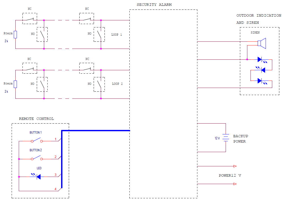
Block diagram of the device.
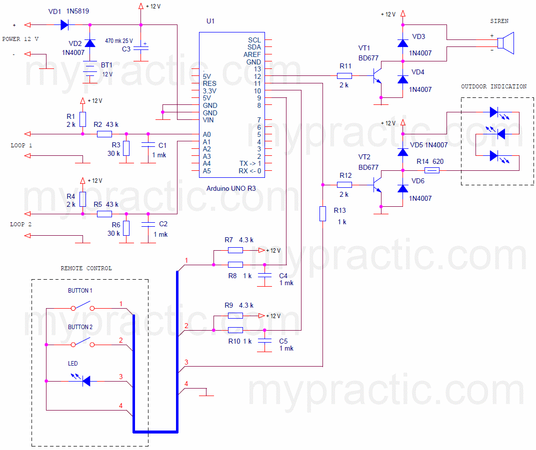
To the alarm control unit are connected:
- 2 standard security loops with:
- NO - normally open sensors;
- NC - normally closed sensors;
- Rterm - terminal resistors.
- Remote Control.
- Outdoor indication unit and sound alert.
- Power supply 12 V.
- Backup power source.
Modes and controls.
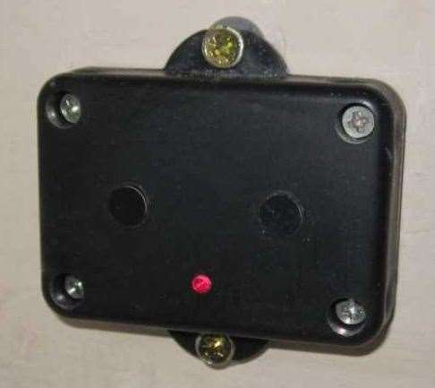
The remote is a small box with one LED and two buttons.
It is better to install the control panel indoors at the entrance door. With the help of it, the alarm is turned on and off, the secret code sets.
When power is applied, the device enters disabled mode (alarm off). Remote LED does not glow. In this mode, the device is during the working day.
The alarm is activated (security mode) by pressing two buttons simultaneously. The LED starts flashing with a frequency of 5 times per second, and after 20 seconds the device switches to security mode, i.e. monitors the status of security sensors.
A time of 20 seconds is necessary in order to leave the premises, close the entrance door.
If during this time (20 seconds) to press any button of the remote control, the device will return to the disabled mode. People often remember something before leaving the room.
20 seconds after switching on, the device will enter security mode. The LEDs of the console and the outdoor display unit flash once a second, the status of the sensors is monitored.
When any sensor is triggered, the LED of the remote starts to flash at a frequency of 5 times per second, and the device counts down the time after which the siren will sound. This time (30 seconds) is necessary in order to disable the alarm by dealing a secret code with the buttons of the remote.
On the remote there are only two buttons. Therefore, the code is a combination of the numbers 1 and 2. For example, the code 2122221 means that you must press the buttons 2, 1, four times 2 and 1. The secret code can contain from 1 to 8 digits.
If the code was dialed incorrectly, it is necessary to press 2 buttons of the remote control simultaneously and repeat the code.
Correctly entered code puts the device into disabled mode.
If the correct code was not dialed within 30 seconds after the security sensor triggered, the siren will turn on. You can disable it by dealing the correct code. Otherwise, the siren will sound for a minute, and then the device will enter disabled mode.
The secret code can only be set from disabled mode. To do this, hold down both buttons of the remote control for at least 6 seconds. Release when the remote control LED lights up. This means that the device has switched to the secret code setting mode.
Now you need to dial a new secret code (from 1 to 8 digits). Pause between button presses should be no more than 5 seconds. Wait until the LED goes out (another 5 seconds). The new secret code will be stored in the non-volatile memory of the controller.
The security alarm statuses is summarized in the table.
| Mode | LED state | Transition condition | Transition to mode |
| ALARM DISABLED | Not lit | Short press two buttons at the same time | Waiting for security mode (20 sec).
It is necessary to go out and close the front door. |
| Hold two buttons for 6 sec. | Setting a secret code | ||
| Waiting for security mode.
It is necessary to go out and close the front door. |
Frequently flashes | Time 20 sec. | SECURITY |
| Press any button (cancel) | ALARM DISABLED | ||
| SECURITY | Flashing once a second | Sensor triggers | Time to turn off the alarm by code (30 sec).
Necessary in order to turn off the alarm by dialing the code. |
| Time to turn off the alarm by code (30 sec).
Necessary in order to turn off the alarm by dialing the code. |
Fast flashing | The correct code has been dialed. | ALARM DISABLED |
| The correct code is not dialed within 30 seconds. | ALARM
(Siren sound) |
||
| ALARM
(Siren sound) |
Fast flashing | The correct code has been dialed. | ALARM DISABLED |
| Time 60 sec | ALARM DISABLED | ||
| Setting a secret code | Lit | Code set | ALARM DISABLED |
Alarm control practically comes down to two operations:
- Leaving the premises - press both buttons of the remote at the same time and close the door.
- Entering the premises - dial the secret code.
Development of the hardware of the device.
Even with all the versatility of the Arduino board, to create a working device, you need to add electronic components to it to connect:
- security loops;
- buttons and LED remote;
- siren and outdoor light indication
- power systems.
Consider these nodes in detail.
Security alarm loops.
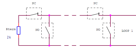
Security systems use special loops to connect sensors. Security loop is a chain of in-line and parallel-connected sensors. Several sensors, both normally closed (NC) and normally open (NO) can be connected to one loop.
The alarm unit monitors the loop resistance. If the resistance is less than the lower threshold or greater than the upper threshold, the device generates an alarm. Normal is the resistance of the loop given by the terminal resistor (often 2 kΩ). If the attacker closes the wires of the loop or breaks them, then an alarm will be triggered.
Let's select the parameters of the loop are the same as in the prototype which uses PIC controller.
| Loop resistance | |
| Nominal value | 2000 Ohm |
| Upper threshold | 5900 Ohm |
| Lower threshold | 540 Ohm |
The loop resistance in the range of 540 ... 5900 ohms is considered normal. When the loop resistance value exceeds the specified limits, an alarm should be triggered.
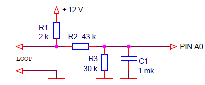
In order for the controller to measure the resistance of the loops, we connect them to the analog inputs of the Arduino board. The circuit for connecting the security loop looks like this:
Resistor R1 sets the loop current. Divider R2, R3 matches the voltage level of the circuit with the input voltage of the analog input (5 V). With the values of resistors on the diagram, the following values of input voltage will correspond to the resistance of the loop.
| Loop resistance | Voltage at inputs A0, A1 |
| 5900 Ohm | 3.6 V |
| 2000 Ohm | 2.43 V |
| 540 Ohm | 1.04 V |
The capacitor C1, together with the resistors, performs analog filtering of the loop signal. To increase the noise immunity of the system, digital signal filtering also occurs in the device.
Remote buttons.
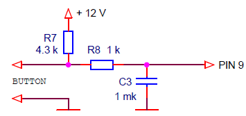
Remote control buttons, as well as security sensors, are connected to the controller with long wires. The signals from them also require analog and digital filtering to ensure high noise immunity and eliminate bounce. Let's connect the buttons to the digital pins of the board: 9 and 10.
When the button is open, the voltage of 12 V is limited to 5 V by the internal protective diode of the microcontroller.
Outdoor indication of the mode and siren.
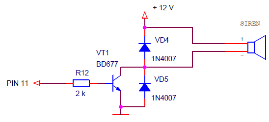
The siren and the light source for external indication of the mode may require significant currents for power. In addition, they are connected to the controller with long wires. Therefore, transistor switches are necessary for control these elements. Here is a diagram of one switch for current up to 2 A.
Resistor R12 limits the base current of the transistor. Diodes protect the transistor from the emission of a signal of a long communication line during switching.
Supply system.
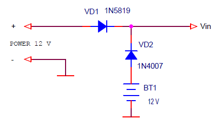
The device is powered by a 12 V power supply. This voltage is suitable for powering both the Arduino board and the siren. To connect the backup battery power, you can use a simple two-diode circuit
As the diode for the main power Schottky diode (VD1) is used. This ensures the priority of the power supply when the output voltage is equal to the backup power supply voltage.
Security alarm circuit based on Arduino UNO R3 board.
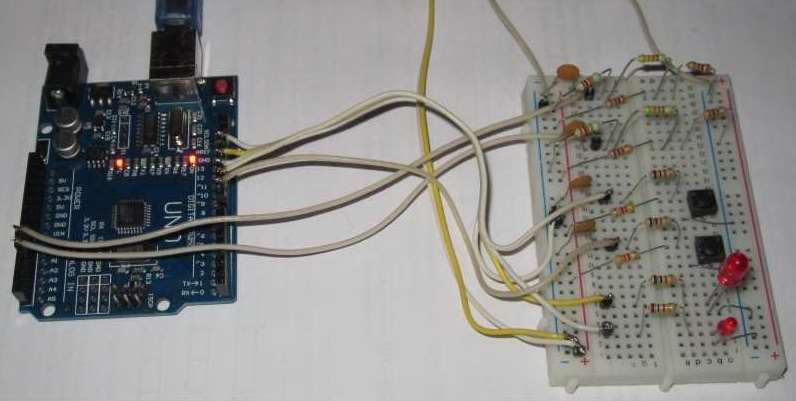
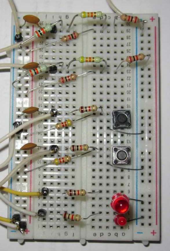
I assembled the sysytem on the breadboard. Instead of the transistor switches I put the LEDs. On this layout, you can fully debug the program, and then create a working version of the device.
The program development.
First of all, we include libraries, assign controller pins, create objects, variables with which we will work:
- two remote buttons;
- timer interrupt;
- software blocks for reading analog inputs for loops and averaging their values.
As a result, we have the following variables with which we will work:
- signs of the state of the remote control buttons:
- button1.flagPress;
- button1.flagClick;
- button2.flagPress;
- button2.flagClick;
- measured average values of the voltage at the outputs of the loops:
- averageShleif1;
- averageShleif2.
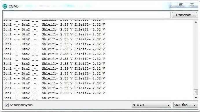
For verification, we send the state of these variables through a serial port to a computer.
Here is the sketch (sketch_17_1.zip).
// security alarm
#include <MsTimer2.h>
#include <Button.h>
#include <avr/wdt.h>
// pin assignment
#define BUTTON_1_PIN 9 // remote control button 1
#define BUTTON_2_PIN 10 // remote control button 2
#define LED_PIN 11 // remote LED and external indication
#define SIREN_PIN 12 // siren is connected to pin 12
#define SHLEIF_1_PIN A0 // loop 1
#define SHLEIF_2_PIN A1 // loop 2
Button button1(BUTTON_1_PIN, 25); // create an object button 1
Button button2(BUTTON_2_PIN, 25); // create an object button 2
unsigned int sumShleif1, sumShleif2; // variables for summing ADC codes
unsigned int averageShleif1, averageShleif2; // sum of ADC codes (average voltage of loops * 50)
int averageCount; // Averaging Counter for ADC Codes (Loop Voltage)
int serialCount; // counter for transferring debug data via UART
void setup() {
pinMode(LED_PIN, OUTPUT); // LED output
pinMode(SIREN_PIN, OUTPUT); // siren output
MsTimer2::set(2, timerInterrupt); // timer interrupt period 2 ms
MsTimer2::start(); // enable timer interrupt
Serial.begin(9600); // initialize the port, rate 9600
wdt_enable(WDTO_15MS); // enable watchdog timer, 15 ms timeout
}
void loop() {
// transfer debug data via UART
// every 500 ms
if ( serialCount >= 250 ) {
// state of buttons
if ( button1.flagPress == true ) Serial.print("Btn1 -_- ");
else Serial.print("Btn1 _-_ ");
if ( button2.flagPress == true ) Serial.print("Btn2 -_- ");
else Serial.print("Btn2 _-_ ");
// voltage of loops
Serial.print(" Shleif1= ");
Serial.print( (float)averageShleif1 * 0.000097656, 2);
Serial.print(" V");
Serial.print(" Shleif2= ");
Serial.print( (float)averageShleif2 * 0.000097656, 2);
Serial.println(" V");
// * 0.000097656 = / 50. * 5. / 1024.
}
}
// interrupt handler, 2 ms
void timerInterrupt() {
wdt_reset(); // reset the watchdog timer
button1.filterAvarage(); // call the filtering method of the button 1 signal
button2.filterAvarage(); // call the filtering method of the button 2 signal
// read the ADC and averaging the voltage values of the loops
// as a result averageShleif = average voltage of the loop * 50
averageCount++; // +1 averaging counter
sumShleif1 += analogRead(SHLEIF_1_PIN); // summation of ADC codes
sumShleif2 += analogRead(SHLEIF_2_PIN); // summation of ADC codes
// check the number of averaging samples (50)
if ( averageCount >= 50 ) {
averageCount= 0;
averageShleif1 = sumShleif1; // overload average
averageShleif2 = sumShleif2; // overload average
sumShleif1 = 0;
sumShleif2 = 0;
}
serialCount++; // counter for transferring debug data via UART
}
Load the program to the board. Start the port monitor. Checking:
- Pressing each button.
- We connect instead of each loop a variable resistor (for example, with a resistance of 10 kΩ). Measure the voltage at the corresponding analog inputs of the board with a voltmeter. Check that the measurement of the voltages at the outputs of the loops is correct.
Then we think about the structure of the program. Variants may be different. I chose this.
Create a variable - mode, which determines the current mode of the program. Set modes:
| mode | Mode | Description |
| 0 | ALARM DISABLED | |
| 1 | SET TO SECURITY MODE | The countdown (20 seconds) to get out of the room and close the door |
| 2 | SECURITY | Monitoring of sensor status |
| 3 | LOCK | Time to turn off the alarm with a secret code (30 seconds) |
| 4 | ALARM | Siren time (60 sec.) |
| 5 | SETTING CODE | Setting a new secret code |
Create in the infinite loop a construct for switching to the desired mode.
if (mode == 0) {
// ALARM IS DISABLED
}
else if (mode == 1) {
// SET TO SECURITY MODE
}
else if (mode == 2) {
// SECURITY
}
else if (mode == 3) {
// LOCK
}
else if (mode == 4) {
// ALARM
}
else if (mode == 5) {
// SET THE CODE
}
else mode = 0;
To switch to another mode, just change the value of the variable mode.
Add in debug data mode.
// mode
Serial.print ("Mode ="); Serial.print (mode);
Now fill the blocks - modes.
All the software blocks I explain in detail in the comments of the program. When filling out each block, you can download the program to the board and check. It is better to debug each block separately, without waiting for errors to accumulate. For example, you can add a module "transition to the mode of installation on the alarm", load into the board and check that by pressing two buttons at the same time, the program switches to mode 1. And does not respond to pressing one button. For this we created a block for transferring debug data to a computer.
Then we add the block “switch to code setting (long holding of two buttons)” and again check that the program goes to mode 5 while holding both buttons pressed for 6 seconds. And so gradually debug the entire program.
Here is the complete sketch of the program: sketch_17_2.zip .
How to install the Button.h library is described in lesson 9. You don’t need to search and install the avr/wdt library. This is the standard library. It is in the software for Arduino.
Load the program into the board. Everything is working right for me.
Which version of the device is better: on the basis of the Arduino board or on the PIC controller PIC12F629?
The second variant, of course, is cheaper, more reliable. But no additional functions can be added to it. There are no free conclusions, and the program is written in assembler. A variant of the device based on the Arduino board can be developed indefinitely. And development, and debugging programs for it is much easier. Decide for yourself. I think it all depends on your purposes and capabilities.
The algorithms of the devices are exactly the same. The alarm system manufactured on the PIC controller
guards the building of our company for almost 2 years, and there are no complaints about the algorithm of work. All employees without any problems learned how to control the device.

