Let's learn how to create program timers in parallel processes. Let's develop a training program for security alarm.
Previous lesson List of lessons Next lesson
In the previous lesson, using the example of a refrigerator controller program, I explained that in real programs for microcontrollers it is necessary to process several tasks simultaneously in cycles with different time periods.
How to create program timers for such cycles. In principle, as well as hardware ones.
- In the system, a single interrupt from the hardware timer is triggered cyclically. The period time is selected as the smallest among the required program timers.
- In the timer interrupt handler, each cycle adds 1 to the counter of the program timer.
- When the counter code reaches the specified value, it is reset to 0. The program timer period is calculated as the time period of the hardware timer interrupt multiplied by the counter reset code value.
Here is an example program with three program timers for 10, 200, and 1000 ms.
#define CYCLE_1_TIME 5 // cycle time 1 (* 2 = 10 ms)
#define CYCLE_2_TIME 100 // cycle time 2 (* 2 = 200 ms)
#define CYCLE_3_TIME 500 // cycle time 3 (* 2 = 1 sec)
volatile byte timerCount1; // timer counter 1
byte timerCount2; // timer counter 2
volatile boolean flagTimer2; // flag of the program timer 2
unsigned int timerCount3; // timer counter 3
void setup() {
}
void loop() {
// program timer 1, period 10 ms
// timer counter is controlled in an asynchronous loop
if ( timerCount1 >= CYCLE_1_TIME ) {
timerCount1= 0;
// program code is called every 10 ms
}
// program timer 2, period 200 ms
// timer counter is controlled in the interrupt handler
if ( flagTimer2 == true ) {
flagTimer2= false;
// program code is called every 200 ms
}
}
// interrupt handler 2 ms
void timerInterupt() {
timerCount1++; // + 1 to timer counter 1
timerCount2++; // + 1 to timer counter 2
if ( timerCount2 >= CYCLE_2_TIME ) {
timerCount2= 0; // reset counter
flagTimer2= true; // set the timer 2 flag
}
// program timer 3, period 1000 ms
// timer counter is controlled in the interrupt handler
// also executed in the interrupt loop
timerCount3++; // + 1 to timer counter 3
if ( timerCount3 >= CYCLE_3_TIME ) {
timerCount3= 0; // reset counter
// program code is called every 1000 ms
}
}
All three timers have their own counters. To each counter in the interrupt handler, 1 is added every 2 ms.
The timer counter 1 is checked in an asynchronous cycle loop(). When its code reaches a value equal to the constant CYCLE_1_TIME, it is reset and the program code for this cycle is executed.
The counter of the second timer is checked in the interrupt handler. When a reset code is reached, it is reset and the flagTimer2 flag is generated. This flag is analyzed in an asynchronous cycle and, with its active state, the code for cycle 2 with a period of 200 ms is executed.
The difference between these methods lies in the fact that when the counter is monitored in an asynchronous cycle, its state should be checked at least the time of the interruption period. If, for example, in an asynchronous cycle the program is delayed by 10 ms, then during this time the timerCount1 counter will count the extra 5 units and will be reset for a larger value. Thus, the cycle time is broken. In the second case, timer counter 2 will be reset in the interrupt handler. With a delay in the asynchronous cycle, the response to program timer 2 will be delayed, but the period of the cycle itself will not be disturbed.
The counter of the third timer is controlled in the interrupt handler and the program code for this timer is also executed there.
There may be different ways of implementing cycles with different periods. There are also program timers synchronized from each other or from a general timer. What way to apply should be solved in a specific problem.
Program for a simplified security alarm.
Let's write a real program for a security alarm. This is a simplified version of my development on a PIC controller. In the future, we will bring the device to a complete analogue of this development at Arduino, and then complicate it by adding GSM control and notification, increase the number of sensors, actuators.
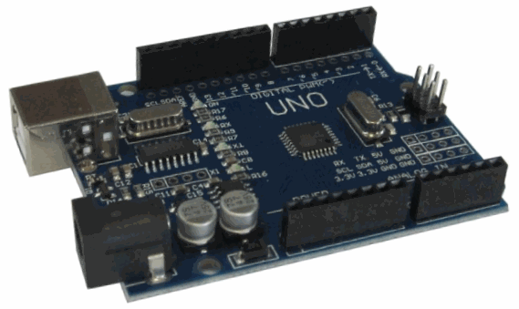
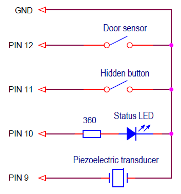
The following alarm components are connected to the Arduino board:
- Door opening sensor. We simulate it with button 1, we believe that in the normal state (the door is closed) the sensor is open, and when the door is open, it is closed.
- Device status LED located above the entrance door:
- off - not lit;
- on (security mode) - flashes once a second;
- triggered (alarm mode) - flashes 4 times per second.
- On / off alarm button. Hidden button at the entrance door. In reality, this can be a masked reed switch, the commutation of which can be produced by a permanent magnet.
- Alarm siren - piezoelectric transducer.
Wiring diagram of these elements to the Arduino board.
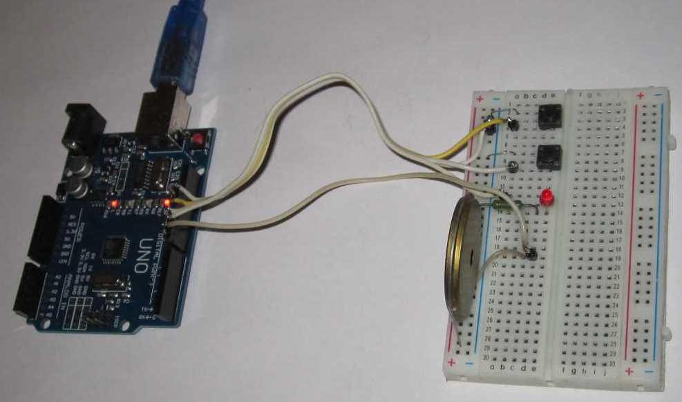
My device layout looks like this.
The algorithm of the device.
- When turned on, the alarm is turned off, the status LED is off.
- Having closed the entrance door, we press the hidden button (or we touch the hidden reed switch with a magnet). The security mode turns on. This is signaled by the status LED flashing once a second. In this mode, the device monitors the status of the door sensor.
- Before you open the door, you must turn off the security mode by pressing the hidden button.
- If the door opens when the security mode is on, the device will go into alarm mode. The siren will start sounding and the LED will flash 4 times per second.
- In this state, the device will stay for 30 seconds and then turn off. You can turn off the alarm earlier pressing the button.
I do not know how much such a security alarm can be used in practice, but for the curriculum it is quite an appropriate task.
The sequence of program development.
The program has a lot of comments, everything should be clear. I pay more attention to the logical sequence of program development.
- Create button objects (Button):
- doorSens - door sensor;
- secretButton - hidden button.
- Create a timer interrupt with a period of 2 ms.
- Call interrupt methods for filtering door sensor and button signals.
- Assign controller pins for all components.
- Set the output mode for the LED and siren.
// simplified security alarm
#include <MsTimer2.h>
#include <Button.h>
#define DOOR_SENS_PIN 12 // door sensor connected to pin 12
#define SECRET_BUTTON_PIN 11 // hidden button connected to pin 11
#define LED_PIN 10 // LED is connected to pin 10
#define SIREN_PIN 9 // siren connected to pin 9
Button doorSens(DOOR_SENS_PIN, 50); // create an object door sensor, type button
Button secretButton(SECRET_BUTTON_PIN, 25); // create object hidden button, type button
void setup() {
pinMode(LED_PIN, OUTPUT); // define the output of the led as an output
pinMode(SIREN_PIN, OUTPUT); // define siren output as an output
MsTimer2::set(2, timerInterupt); // set the timer interrupt period 2 ms
MsTimer2::start(); // enable timer interrupt
}
void loop() {
// no code yet
}
// interrupt handler 2 ms
void timerInterupt() {
doorSens.filterAvarage(); // call signal filtering method for door sensor
secretButton.filterAvarage(); // call signal filtering method for hidden button
}
Now we have all the components of the system in the program. At this stage, you can check the hardware of the device. To do this, you must temporarily make a simple logical connection between the buttons, the LED and the siren in the loop () cycle. And make sure that the LED responds to opening the door or pressing the button. We did this in previous lessons.
If you do not check the hardware, then at least it is necessary to compile the program to check for formal errors.
Our siren is a piezoelectric pass emitter. In order for it to emit the sound of an alarm, it is necessary to form a signal of a variable form on it. Let's make a program block for the formation of this signal. We simply invert the state of the corresponding output in the fastest loop - the interrupt handler. To enable and disable the siren create a flag.
boolean sirenOn; // sign of siren activation
In the interrupt handler, we write:
// siren control unit
if (sirenOn == true) digitalWrite (SIREN_PIN,! digitalRead (SIREN_PIN));
To test, you can insert in loop()
sirenOn = secretButton.flagPress; // check the siren
When you press the hidden button, the siren (piezo emitter) will emit an alarm signal. Do not forget to delete after checking.
The structure of the program.
Let's think about the structure and modes of the program. The simplest and most logical structure is as follows. In an asynchronous cycle, blocks are allocated - modes. In each block, the program runs in cycles, and jumps to other blocks (modes) under certain conditions using the goto operator. Logically, the following device operation modes can be distinguished:
- the alarm is disabled (DISABLED MODE);
- the alarm is on (SECURITY MODE);
- the alarm has triggered (ALARM MODE).
Let's create such program blocks, each with an infinite loop and a label at the beginning to go to them.
void loop () {
// ---------------------- DISABLED mode ------------------------
guard_off:
while (true) {
}
// ---------------------- SECURITY mode ------------------------
guard_on:
while (true) {
}
// ---------------------- ALARM mode ------------------------ ----
alarm:
while (true) {
}
}
It is believed that the use of the goto operator should be limited. But in cases when this operator simplifies the understanding of the program logic, makes it easier to read, the goto application is considered justified. We have such a case. Logically, there can be a transition to any block from any. Operators break, continue, etc. such transitions do not provide.
Fill each block with a code.
For block DISABLED MODE:
- LED is off;
- the siren does not sound;
- if the button is pressed, then the transition to SECURITY MODE.
//---------------------- DISABLED MODE --------------------------------
guard_off:
while (true) {
digitalWrite(LED_PIN, LOW); // LED is off
sirenOn= false; // siren does not sound
// if the button is pressed, go to the SECURITY MODE
if ( secretButton.flagClick == true ) {
secretButton.flagClick= false;
goto guard_on;
}
}
You can try to download the board. The LED does not light, the siren does not sound.
For the block SECURITY MODE:
- the LED flashes once per second;
- the siren does not sound;
- if the button is pressed, the transition to the DISABLED MODE;
- if the door sensor has triggered, the transition to the ALARM MODE.
To realize the flashing LED, we declare the ledTimeCount time counter and two constants: TIME_LED_PERIOD and TIME_LED_ON. The first one sets the blinking period of the LED (500 for 1 second), the second defines time of the on state (100 for 0.2 s). The time counter is increased by 1 every 2 ms in the interrupt handler, and the LED is controlled by simple logic in the SECURITY MODE unit.
#define TIME_LED_PERIOD 500 // LED flashing period time (* 2 ms)
#define TIME_LED_ON 100 // LED On Time
unsigned int ledTimeCount; // time counter for LED
//---------------------- SECURITY MODE --------------------------------
guard_on:
while (true) {
sirenOn= false; // siren does not sound
alarmTimeCount= 0; // reset alarm time counter
// LED flashes once per second
if ( ledTimeCount >= TIME_LED_PERIOD ) ledTimeCount= 0;
if ( ledTimeCount < TIME_LED_ON ) digitalWrite(LED_PIN, HIGH);
else digitalWrite(LED_PIN, LOW);
// if the button was pressed, the transition to DISABLE MODE
if ( secretButton.flagClick == true ) {
secretButton.flagClick= false;
goto guard_off;
}
// if the door sensor has triggered, the transition to ALARM MODE
if ( doorSens.flagPress == true ) goto alarm;
}
//------------------- interrupt handler 2 ms ---------------------
void timerInterupt() {
// ………….
ledTimeCount++; // LED flashing time counter
}
We load the program to the Arduino board. We check that pressing the button puts the device into SECURITY MODE (the LED flashes). The next press of the button returns to the DISABLED MODE (the LED is off).
It remains to fill in the ALARM MODE block:
- the LED flashes 4 times per second;
- the siren sounds;
- if the button is pressed, the transition to the DISABLED MODE;
- if 30 seconds have passed - the transition to the DISABLED MODE.
Add the TIME_LED_ALARM constant - the time of the LED flashing during ALARM. Use the same counter for the LED.
To count the time in the ALARM MODE, we announce the alarmTimeCount counter and the TIME_ALARM constant - the time in the ALARM MODE (30 seconds). Before entering the ALARM MODE, the counter must be reset.
That's all. The program is ready. Final sketch:
// simplified security alarm
#include <MsTimer2.h>
#include <Button.h>
#define DOOR_SENS_PIN 12 // door sensor connected to pin 12
#define SECRET_BUTTON_PIN 11 // hidden button connected to pin 11
#define LED_PIN 10 // LED is connected to pin 10
#define SIREN_PIN 9 // siren connected to pin 9
#define TIME_LED_PERIOD 500 // LED flashing period time (* 2 ms)
#define TIME_LED_ON 100 // LED On Time
#define TIME_LED_ALARM 62 // time period for the LED to flash when ALARM (* 2 ms)
#define TIME_ALARM 15000 // time in ALARM mode (* 2 ms)
Button doorSens(DOOR_SENS_PIN, 50); // create an object door sensor, type button
Button secretButton(SECRET_BUTTON_PIN, 25); // create object hidden button, type button
boolean sirenOn; // sign of turning on the siren
unsigned int ledTimeCount; // time counter for LED
unsigned int alarmTimeCount; // alarm time counter
void setup() {
pinMode(LED_PIN, OUTPUT); // define the output of the led as an output
pinMode(SIREN_PIN, OUTPUT); // define siren output as an output
MsTimer2::set(2, timerInterupt); // set the timer interrupt period 2 ms
MsTimer2::start(); // enable timer interrupt
}
void loop() {
//---------------------- DISABLED MODE --------------------------------
guard_off:
while (true) {
digitalWrite(LED_PIN, LOW); // LED is off
sirenOn= false; // siren does not sound
// if the button is pressed, go to the SECURITY MODE
if ( secretButton.flagClick == true ) {
secretButton.flagClick= false;
goto guard_on;
}
}
//---------------------- SECURITY MODE --------------------------------
guard_on:
while (true) {
sirenOn= false; // siren does not sound
alarmTimeCount= 0; // reset alarm time counter
// LED flashes once per second
if ( ledTimeCount >= TIME_LED_PERIOD ) ledTimeCount= 0;
if ( ledTimeCount < TIME_LED_ON ) digitalWrite(LED_PIN, HIGH);
else digitalWrite(LED_PIN, LOW);
// if the button was pressed, the transition to DISABLE MODE
if ( secretButton.flagClick == true ) {
secretButton.flagClick= false;
goto guard_off;
}
// if the door sensor has triggered, the transition to ALARM MODE
if ( doorSens.flagPress == true ) goto alarm;
}
//---------------------- ALARM MODE --------------------------------
alarm:
while (true) {
sirenOn= true; // siren sounds
// LED flashes 4 times per second
if ( ledTimeCount >= TIME_LED_ALARM ) {
ledTimeCount= 0;
digitalWrite(LED_PIN, ! digitalRead(LED_PIN));
}
// if the button is pressed, the transition to DISABLE MODE
if ( secretButton.flagClick == true ) {
secretButton.flagClick= false;
goto guard_off;
}
// check alarm time (30 sec)
if ( alarmTimeCount >= TIME_ALARM ) goto guard_off;
}
}
//------------------- interrupt handler 2 ms ---------------------
void timerInterupt() {
doorSens.filterAvarage(); // call signal filtering method for door sensor
secretButton.filterAvarage(); // call signal filtering method for hidden button
// siren control unit
if ( sirenOn == true) digitalWrite(SIREN_PIN, ! digitalRead(SIREN_PIN));
ledTimeCount++; // LED flashing time counter
alarmTimeCount++; // alarm time counter
}
A sketch of the program can be downloaded at this link.
We load the program to the board and check. Opening the door is simulated by pressing the first button. Everything is working.
In order for the device to work in real conditions, it is desirable to refine the electrical circuit, as is done here. But better wait, after a few lessons we will write a program that fully performs the functions of the prototype. And later we will add GSM alert and remote control.
The next lesson will be devoted to transferring data over a serial UART interface and debugging programs on the Arduino.


